
You are using an out of date browser. It may not display this or other websites correctly.
You should upgrade or use an alternative browser.
You should upgrade or use an alternative browser.
-
You can now help support WorldwideDX when you shop on Amazon at no additional cost to you! Simply follow this Shop on Amazon link first and a portion of any purchase is sent to WorldwideDX to help with site costs.
MC145106P info needed
- Thread starter Techno1
- Start date
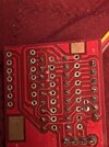
Its all really easy to see if you overlay the 8719 pinouts with that socket and the 145106 pinouts over the spot it was removed. Pins 1-4 on the socket (on the 8719) are inverters the 145106 doesnt have. Those sets of pins tied together are the unused inverters and are tied to one state or another to prevent noise (and they forgot to tie down an inverter too) Edit: looks like they actually diasy chained three and did nothing with the input/output of the chain, not sure what their plan was there). The 4 wires going to the rotary switch control P6, P7 and P8 of the 145106 chip.
A 7414 chip would work for an inverter chip no it won't, too low of voltage rating, other chips suggested below.
looks like you lost a couple pads...
looks like you lost a couple pads...
Last edited:

Thanks for the info.
Yes lost some pads no big deal as the trace and pads real small and thin traces.
So Ill see if i have a 7414 hex inverter to try.
I will post back with update
Yes lost some pads no big deal as the trace and pads real small and thin traces.
So Ill see if i have a 7414 hex inverter to try.
I will post back with update
I think I'm wrong about the 7414, that one doesn't have a high enough voltage rating. Let me look what one does.Thanks for the info.
Yes lost some pads no big deal as the trace and pads real small and thin traces.
So Ill see if i have a 7414 hex inverter to try.
I will post back with update
I have some mc74hc14an hex inverter i think are the same.
also have some sn74als95an and sn74als04bn bot hex inverters
also have some sn74als95an and sn74als04bn bot hex inverters
MC14069 and CD4069 are rated at 18v. The 7404 ones are also too low of voltage if it is on the 8v regulator. Those 7404's and 7414s are rated at 7v.
dont have any of those will have to order a few to see if they will work.
thanks for your help and will update when I get some Hex chips and try them.
thanks for your help and will update when I get some Hex chips and try them.
Brandon the the CD4069 worked great thanks for the suggestions.
Im here in Boston Ma.
I had on laying around gave it a try and works
Im here in Boston Ma.
I had on laying around gave it a try and works
I have to apologize to anyone who used my 8719 PLL calc. The calculator is centered around AM frequencies, but unfortunately, I had put in the tripler crystal frequency as it is printed on the can. The problem with doing that is that 11.1125 is for USB, not AM. Therefore, when I highlighted the channels that are on the dial and their associated N codes, it was off by a few digits. I should have put 11.1116666666666666666666666666666666666 into that tripler box, not 11.1125.
Throwing myself under the bus so the next person don't make the same mistake. If you use my calc from several posts back, change that tripler value accordingly and ignore the green "normal channels" I had highlighted.
Throwing myself under the bus so the next person don't make the same mistake. If you use my calc from several posts back, change that tripler value accordingly and ignore the green "normal channels" I had highlighted.
Last edited:
Hi all Im back at it again with some questions.
This kit i have installed in a pc-385 RS trc 490 same a s a washington and other radios is working good range is set to 28.045 to 26.495 vco limit of course.
See pictures of the board with the MC145106 pll replacing the mb8719 or the mb8734 will work with replacing either pll as long as the radio has the 11.3258 xtal.
Will work with the 11.1125 but will get different frequencies.
There is a 3 position rotary
there is a toggle to get missed high and low bank.
there is a toggle to get 41-44
there is a toggle for a 10kc jump.
So on the channels no missed channels from 28.045 to 26.495.
I have added a freq counter to monitor all the channels, made in a small box with the mounted switches. Freq counter has the 7th digit also with a momentary sw on back can do 6 or 7 digits. Did not alter the radio.
To get radio back to normal unplug module and re-install the mb8719 and back to regular 1-40chs.
****So my big big question is can the mc145106 be modded to get the 5 kc jump/half channels but still retain the channels it now has. I know the 5kc mod is to shift some traces and use pin 6 to ground and pin 17 to a toggle switch.
I did not want to do that on the radio so was thinking of doing on the pc kit board, would that work without altering the channels I have now?
Open black socket has another socket that allows it to plug into radio socket on main board.
The white connector is a 10 pin to wire to 3 position rotary and the 3 toggle sw
switches
Last edited:
Here's the routine. First, ground pin 6 to select the 5 kHz reference. Next, unhook all the channel selector wires and move them up one bit. This means moving them all "down" one pin number. Pin 17 will go to a toggle switch, for your 5 kHz step. Ground for even "10" channels, high for channels to end in 5 kHz like the CB channels.can the mc145106 be modded to get the 5 kc jump/half channels
The wire from the channel selector to pin 17 gets moved to pin 16. The pin 16 wire now goes to pin 15 and so on, until you get to pin 9. Whatever used to be connected to pin 9 now just gets left loose.
The 5 kHz 'ripple' on the VCO tuning voltage might not get filtered properly by the 10 kHz filter now in line with the VCO tuning voltage. Might work just fine, or might need some tweaking.
73
Nomad radio.
thanks for the info.
Do you think i will be able to keep the channel mod working still if i swap the pins out?
thanks for the info.
Do you think i will be able to keep the channel mod working still if i swap the pins out?
Uncharted territory. Without a schematic I would be shooting in the dark. Just the same, any mod that is upstream from pins 8 through 17 should still work as before. All we did was divide the frequency we get from each binary step in half grounding pin 6. Moving the wires from pins 17 to 8 each "up one" position is the same as multiplying by two. This gets you back to the same frequencies you had before the change. If you only change pin 6 this would change the PLL's frequency coverage. Moving the PLL's input pins "up one" moves the coverage back where it was.
73
73
Last edited:
dxChat
- No one is chatting at the moment.
-
-
-
dxBot:63Sprint has left the room.
-
dxBot:kennyjames 0151 has left the room.
-