• You can now help support WorldwideDX when you shop on Amazon at no additional cost to you! Simply follow this Shop on Amazon link first and a portion of any purchase is sent to WorldwideDX to help with site costs.

Modified Vector 4000

Perhaps that isnt wise in this case,

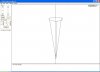
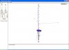
I guess the file already has between 100...200 wires. ( a lot of wires take up for the ring) .
So that would be a very large Jpeg?..

I can send the eznec file to who ever wants it no problem just contact me at:
19sd348@planet.nl and ill send the file as a .ez file.

The file sofar has limitation. As mentioned i have asked kirk who at his turn asked allen to verify the file. Now to my believe these guys are the top of the antenna world..
They are at least a lot closer than where we are standing lol...

If that is done we can say with certainty what the antenna does.
So first confimation of the file (since i am not a expert either!)
And than we can post findings...
Trust is good....confirmation is better !

73 H.

Well Henry, 200 wires is a lot more than I expected. I figured maybe 26 wire would cover it. If that's the case, then you guys really missed the results target when ya'll made the first model with only 14 wires.

How about you posting your Eznec results on your own Website then. That might be better.

Eddie
 
Hi Marconi !

The first idea was to simplify the antenna to get some results is the antenna was capable of moddeling. the diameters of the antenna were not know etc.
We did manage to get satisfied results with that.
In that case you can continue to work on the antenna and put more effort in it.
You have to see it works and can be done, before one continues.

Look at it as the ever first yagi... that wasnt a 2x 10 elements stacked etc..
it probarbly was a simple 2 or 3 element from there you pick up and continue.

The only reason why there are so many wires is cause the antenna has a loop.
now to get a loop you need to have many points on the XYZ ax...
Thats the reason the first model only had a square 'loop" as that only "cost" 4 wires.
A good round loop will take up many many more.

The rest of the antenne doesnt take that much wires from my mind 8 for the radials and perhaps 8 for the main radiator.

Anyway...as mentioned the questions are brougth up to other people...
Hang in there....we will get there :))

Kind regards,

Henry.
 
The only reason why there are so many wires is cause the antenna has a loop.
now to get a loop you need to have many points on the XYZ ax...
Thats the reason the first model only had a square 'loop" as that only "cost" 4 wires.
A good round loop will take up many many more.

This answered the question that was on my mind. I had assumed that was the case.
 
When working on this antenna in EZNEC one should check the average gain test as outlined in the instructions. I'm still confused why wire # 1 is in the model? With it in place it is adding losses into the model that according to the instructions could be falsely adding as much as 1.6 db. What is the purpose of wire 1 and why not remove it and just place the source 10% above the bottom of the main radiator like the actual antenna? The gain shows less but the model then indicates nearly no loss in the average gain test with the maximum accuracy. Supposedly.
 
Hi SW!


Could it be: If you loose wire one you do not have a "DC" connection between the radials and the main radiator
If you change the feedingpoint with 10 precent it isnt where it is in "real" life ?
Just thinking out loud...at the office now no eznec around..

I have also asked the questions on other forums...ill see what pumps up.
The biggest suprise i have so far is that the length is beyond the "optimum" length for a vertical.
If you take a look at a normal J-pole one could expect about 2,5dBI acoording eznec.
The V.4000 is capable of producing around 4 dBI wich is a significant difference.
So although all the thougths go out that it just is a normal J-pole i wonder where the additional gain comes from...

Ill find out... 73. H.
 
I think I should have asked why are there two wires used to make the main radiator? We have a short wire # 1 with the source applied to it, connected to the long wire # 10. NEC says that a short wire (less then .2 wavelength) should not have a source applied to it. This produces inaccuracies due to loss that can be seen when you run the average gain test. I only know this because I stayed up to 2 AM reading the EZNEC instruction book last night. I had just been holding off on that until I was sure I didn't know what I was doing.

I removed wire #10 and extended wire #1 to the full length of the main radiator. The source on the Sigma IV is not applied at the bottom of this radiator as if it were directly fed at the base. The gamma match shunt feeds the radiator at approximately 10% above the DC shorted base. This is the point where the strap connects the gamma to the main radiator. I thought the model source should be in the same place.

Both the removal of the second wire from the main radiator and moving the source up 10% caused the gain to drop. The good news is this removed nearly all loss in the average gain test. I suspect there are problems with placing the source on wire #1 when it is so short.
 
I know you guys are busy modeling, and trying to figure out the vector4000, so this may be just a nuisance. . . However, I've read that some suspect the vector is a fancy form of j-pole, and/or some kind of sleeve antenna. So I put this together to see how it stacked up against the model. The truth is, as unfamiliar as I am with the finer points of antenna theory, this thing tuned without any matching system except itself as described :

Now this antenna is end fed. It isn't a center-fed dipole. The center radiator descends from top to bottom through the larger lower sleeve/pipe. Both are connected at the bottom - shield to lower outside sleeve, center wire to inner center element with coax choke beneath.

The total length is about 223 inches of which, the upper 195.5" is 1/2" EMT, the last 27.5" is #14 wire, 3.5" of which sticks out beyond the bottom of the sleeve. The lower/outer sleeve is 80.25 inches. The sleeve is a pre-sized length of aluminum yard lamp pole - almost 3" diameter, inside ID is 2.8125".

SWR -

28.755 ---------------- 2.0:1
28.305 ---------------- 1.8:1
27.855 ---------------- 1.7:1
27.405 ---------------- 1.4:1
27.205 ---------------- 1.2:1
26.965 ---------------- 1.1:1
26.850 ---------------- 1.0:1
26.515 ---------------- 1.2:1
26.065 ---------------- 1.6:1
25.615 ---------------- 1.9:1
25.165 ---------------- 2.0:1

Are there similarities in these antennas? I have no modeling software, so I cannot model it, but is this a real (actually useful) antenna?
It talks and receives. The other one is higher, so it does better it seems ( I take this back. The jury is still out. I got better receive from this one with some local truckers a few minutes ago).

If this is too off track it's okay if you tell me so. I'm just curious. :unsure:
 

Attachments

  • 3731b.JPG
    3731b.JPG
    11.4 KB · Views: 117
Last edited:
RE: Sigma4 and Vector

Thought I would start at the begining with the AV174 Sigma4 pdf posted earlier in the thread to create an eznec file. From the file I have the following
information.

Vert info:
.500" @ 45"
.625" @ 38"
.750" @ 30"
.875" @ 30"
1.00" @ 38"
1.125" @38"
1.250" @38"
1.375" @35"
1.500" @88" (16.5" + 71.5" for connector/radial bracket)

380 total inches. If you allow for a 4" overlap between taper sections
380-32 = 348" 348 minus the 16.5" of 1.5" tube below the base bracket
= 331.5" or 27' 7.5''

Loop info:
4- .375" @ 24" 96" total.
94.5" as built with .375' overlap.

Radial info: 3 radials 2 tapers each.
.375" @ 34"
.500" @ 60"
90.5" as built with 3.5" overlap

When modeled I connected the radials directly to the 1.5" tube. Have to check the manuals for the tube correction to simulate a bracket. Also, the
radials in the model are 90.5" @ 1/2" tube not tapered. Still working on that.
The source is near the base. The manual states the gamma tap is 33" up from the base bracket. You can change the segments on wire #2 to get the proper % placement for the source point if needed. ( not sure if it is proper to do it) If anyone is interested in the eznec file to work with pm me
and I will send it. Hope to get the exact info for the Vector 4000.
Should have EZNEC Pro/4 with the nec 4 engine soon.
Maybe it will help with the close wires and sharp degree bends.
 

Attachments

  • sigma4-2.JPG
    sigma4-2.JPG
    44.2 KB · Views: 22
  • sigma4-1.JPG
    sigma4-1.JPG
    47.5 KB · Views: 21
Last edited:
Good work Dxer. How about pattern, bandwidth, currents, and wires if available? I think you got the source right and that S/B an improvement on results.
 
Last edited:
I have been running the Sigma model through eznec and Antenna Model.
Both look very close in results. Here are some of the elevation plots at different wavelengths in height: 1/2, 3/4, 1, and 1.5wave up. The swr plot is from Antenna Model. Its with a conjugate match
to show the bandwidth.
 

Attachments

  • SIGMA SWR.JPG
    SIGMA SWR.JPG
    167.9 KB · Views: 25
  • SIGMA @ 1.5 WAVE.JPG
    SIGMA @ 1.5 WAVE.JPG
    38.5 KB · Views: 122
  • SIGMA @ 1 WAVE.JPG
    SIGMA @ 1 WAVE.JPG
    38.3 KB · Views: 123
  • SIGMA @ .75 WAVE.JPG
    SIGMA @ .75 WAVE.JPG
    38.3 KB · Views: 119
  • SIGMA @ .5 WAVE.JPG
    SIGMA @ .5 WAVE.JPG
    38.3 KB · Views: 122
DXer, The radials on the new Vector are spaced 7/8 of an inch from the radiator at the base. The old Vector was spaced 5/8 of an inch. I also notice the radiation currents shown in pink on your model do not line up properly with the end of the radials and loop. They should be lined up so the loop is placed right where the dip in current is. This provides the maximum gain. That means your radials need to be longer or your radiator needs to be shorter. The two antennas you are working with are very similar. The one with the aluminum pipe at the base is a sleeve monopole and is a close cousin to the Sigma design.
 
Last edited:
Hello Shockwave. Thanks for the info on the 7/8" spacing on the radials at the base bracket. I still have to taper the radial elements and read up on the tube correction factor when simulating a bracket. ( Short wires at the base like in Henrys EZNEC file. W6QHS/W6NL or W2PV info.

I'm only working with the original Sigma4 that I posted the info for. I used two wires to make the 88" 1.5" section to make it easier for someone with the file to see the bracket / radial attachment point. Henry will send me his updated Vector 4000 file so I have the new dimensions on the antenna to compare the performance in Eznec with the Sigma4 file I am working on.

I'd rather not assume any dimensions on the tubing lengths and tapers from the Sigma file to make the Vector. If you want the Sigma4 file I have I'll send it to you.
 
RE: Vector

Decided to go ahead and convert the Sigma4 file into the Vector from the
info sheet Marconi posted earlier. The Vector is shorter so the top tube will now be .625" on the Vector.

.625" @ 28.7"
.750" @ 40"
.875" @ 40"
1.0" @40"
1.125"@40"
1.250"@40"
1.375"@50"
1.5" @55" ( 2 wires 14.5" + 40.5" )

Hoop is the same at 94.5" total.
Radials 4 at 106.8" each
From the bracket to the top of the antenna is 319.2" or 26.6'
Total with the 14.5" lower section is 333.7"

To get the current dip at the hoop as suggested by Shockwave I had to
shorten the .625" tip by 15.8" making the antenna from bracket to tip now
303.332" or 25.27'. The last plot is an overlay of the original Sigma 4 design
from earlier and the 2 Vectors. normal 26.6" and modded 25.27" all at one
wavelength high.

Looks like the upper lobes on the original Sigma design have been compressed
to form gain into the lower lobes. (Longer radials - shorter vert ). Hope I'm not taking up bandwidth here jumping in the last few days but I enjoy the topic and all the hard work cut and try in the field by all.
 

Attachments

  • VECTOR 26.6A.JPG
    VECTOR 26.6A.JPG
    19.3 KB · Views: 122
  • VECTOR 26.6B.JPG
    VECTOR 26.6B.JPG
    29.5 KB · Views: 111
  • VECTOR 25.2A.JPG
    VECTOR 25.2A.JPG
    19.8 KB · Views: 110
  • VECTOR 25.2B.JPG
    VECTOR 25.2B.JPG
    34.7 KB · Views: 111
  • 3 PLOTS.JPG
    3 PLOTS.JPG
    42 KB · Views: 111
Decided to go ahead and convert the Sigma4 file into the Vector from the
info sheet Marconi posted earlier. The Vector is shorter so the top tube will now be .625" on the Vector.

.625" @ 28.7"
.750" @ 40"
.875" @ 40"
1.0" @40"
1.125"@40"
1.250"@40"
1.375"@50"
1.5" @55" ( 2 wires 14.5" + 40.5" )

Hoop is the same at 94.5" total.
Radials 4 at 106.8" each
From the bracket to the top of the antenna is 319.2" or 26.6'
Total with the 14.5" lower section is 333.7"

To get the current dip at the hoop as suggested by Shockwave I had to
shorten the .625" tip by 15.8" making the antenna from bracket to tip now
303.332" or 25.27'. The last plot is an overlay of the original Sigma 4 design
from earlier and the 2 Vectors. normal 26.6" and modded 25.27" all at one
wavelength high.

Looks like the upper lobes on the original Sigma design have been compressed to form gain into the lower lobes. (Longer radials - shorter vert ). Hope I'm not taking up bandwidth here jumping in the last few days but I enjoy the topic and all the hard work cut and try in the field by all.

First off, the measurements I provided are only estimates in most cases and information from Mack and the Manual in others. I think this New Vector is likely to be just as long as my Antennas Specialists Sigma 4 @ 27'7" from bottom of the hub to the tip. Note that the New Vector does not show measurements including the top wire basket, so I guess it is not figured in the overall length either. And for sure the 5 section whip section is only a guess. Dirty White Boy is the only one I know that might have one down so it can be measured accurately, if he has not sold it.

Dxer, among other ideas I have about the Sigma4 I have commented before that it responds like a collinear antenna somehow. However, I have a little different slant regarding your compression idea. I use the term compression specifically in my explanation. I think you used it generically referring to the lobes in the images you just produced.

A long time before I talked about the collinear ideas, I was convinced that there was an affect from the top 1/2 wave that compressed down, lowering the 1/4 wave pattern in order to maximize the gain we see with the lower lobe of this antenna's modeling images. I didn't come by this compression thought on my own. I remember reading another opinion somewhere that explained this was how the 3/4 wave Sigma4 worked---and it seemed to make sense. As I recall, the article was trying to justify how a 3/4 wave radiator could work so well, when most evidence was that anything longer than .64 was no-way-no for gain in HF.

I think I see an in-phase current in the images of the Vector you guys have produced, a current in the 1/4 wave area that is said to be constructive to the 1/2 wave part of the antenna. IMO, this too may account for the gain and leaves me with mixed feelings.

Its been a while since I read the article and unfortunately I don't remember the source. I think it was justified however, because a typical 3/4 wave ground plane pattern is shown to be out of phase at this important point, between the top 1/2 wave and the lower 1/4 wave---sort of like a 5/8 wave ground plane. IMO, this should account for a lack of performance even when compared to the 5/8 wave if true. I've also hear it described that the top 1/2 wave does not show much current flowing and thus accounts for the reduced gain in the 1/2 wave lobe area.

Since I don't see physical evidence of collinear construction in the Sigma I'm prone to believe that it is this compression that occurs, and that results in the gain we see.
 
It was the late L.B. Cebik that said the Sigma was a non apparent collinear radiator. Bob 85 has posts in this forum with regards Cebik's comments. Cebik suggests that this collinear is somehow formed by folding the radials upward. All I can say is if you place the radials in any orientation other then folded up, this antenna is a complete flop! I think the gain is all about the radials causing the bottom section to radiate in phase with the top. Fold the radials down on the same 3/4 wave radiator and the antenna has less gain on the horizon then a 1/4 wave.
 

dxChat
Help Users
  • No one is chatting at the moment.