• You can now help support WorldwideDX when you shop on Amazon at no additional cost to you! Simply follow this Shop on Amazon link first and a portion of any purchase is sent to WorldwideDX to help with site costs.

Outdoor Loop

Sorry about the 'NVIS'/'Nevis' thingy, even misspelled you get the idea.
I used an antenna called a NVIS to do phone patches during 'Desert Storm'. That 'short range' type of qualification/classification is very vague to say the least. Admittedly, the propagation was much 'better' than now, but still, that 'straight up' thingy isn't as sure a bet as you might think.
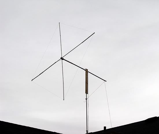
About that 'diamond' shaped quad thingy. Yes, it can work and be directional. There are several antennas of that sort. Would two quads be better than using two other types of antennas (or more than two)? I don't know, but I sort of doubt it. It would be the equivalent of two single element quad antennas pointed in different directions. Using dipoles instead of a loop means that the resulting antenna would be a two element directional antenna (Super Scanner??). Different shaped/styles of antennas have different characteristics in them selves. I like loops, but they get sort of bulky/cumbersome, you know?
- 'Doc

I'm wondering if it would have omni-directional properties, and if so would there be good gain, and decent bandwidth . . .
 
no no no, you have to look at the green dot! you would have a 12 degree angle at the highest gain lobe of 5.56dbi or about 3.5dbd!

hey marconi, can you do that model looking straight down on it from space? i want to see the polar pattern.

I agree with you NB. Here are the physical view and azimuth plot of Homer's quad idea with the feed points to the sides.

There is a Freecell discussion on this forum about this SE antenna, and I think he is suggesting the opposing wires are co-phase fed and both are radiating a bid-directional pattern like I think you are imagining.

View attachment Homer's quad idea from the top.pdf
 
From the looks of that radiation pattern, it looks nearly perfectly omni-directional.

The co-phase #2 model does seem to produce a nice omni pattern in free space with the co-phase setup turned on, but it too has a very bad match that would have to be fixed. As it is now this one shows SWR over 20:1 and both resistance and reactance are way high.

I'll try to model the SE antenna tomorrow maybe. Like I said earlier, this one has the wires insulated at each end, unlike my original model of your idea for two quad elements bisecting each other.

So far all iterations I have made result in very high matching numbers, and to fix those may result in additional losses and reduced gain. I also note that these buggers don't allow me to attach a conductive mast to the bottom without the pattern and currents going to heck in a hand basket and I don't seem able to reproduce anything near the 0 degree maximum angle that SE shows on their old Website. Maybe FreeCell was right. The wires may be co-phased, or delay phased in such a fashion with two opposite wires...each radiating together when used to produce a bi-directional beam pattern. The RF may be radiating from each wire like a dipole and not bisecting the quad loop as we typically imagine.

BTW, unless the match is close, I'll not be able to show any bandwidth. The SWR generator will be off the chart at 20:1 SWR or more. Does your quad show a much better bandwidth than your sleeved dipole or your yagi beam?
 
Maybe I can get a short coax on the loop sometime tomorrow and check for bandwidth.
With the long coax back to the shack 2.0:1 runs from 29.195 to 26.385. Because your model has no coax on it, I want to go close to the antenna to see what it really is. On the SWR meter it is similar, except it drops off the lowest frequency the radio is capable of - 26.000 - before it gets to 2.0:1.

So until I am satisfied by putting the MFJ-209 on it with much less than 90 feet of coax, it appears to have more bandwidth than the other antennas.

Tonight with no DX on the band i was able to converse with several stations ranging from 30 to 60 miles North and Northwest of me through the hills on the Sigma4. I could not read those stations with the loop. Clearly the behaviors of each are completely different.
 
maybe feed one loops 75ohm directly and the other through the 75ohm then a 1/4 wave of 50ohm before it gets to the t connector putting it 90 degrees out electricaly
 
Hello Guys !

I wonder why that nvis thingy is still coming back ?
After re-reading the thread i found out i was probarbly the one who started using the word NVIS. So my appologize for that.

However, I have stated the antenna is quite well known for nviss use.
(heck i designed and installed them in Afghanistan)
And i have stated it is not such a good DX antenna for 27 Mhz.
That does not mean I have said it is a NVIS antenna for 27 Mhz...

Futher down the thread i read other people talking about NVIS antennas "types" aswell.

Responses on the other hand seem to focus more about nvis comunication on 11 meter is not possible (for as far as we know now) And yes that is of course very true.

But please do not forget that although the both are related they are not always together.

As far as i scanned the thread, nobody said anything about NVIS communication..please bare that in mind.

@ Needlebender..

To come back to your questions...Yes the higher angles 35-40 degrees are indeed welkomed for Sproadic E, Though some lower angles are used for sproadic e aswell.
It is similair to what w5lz said regading NVIS angles...though the "bunch" migth come from one directions some will come in under a different angle.

Regarding ground gain. As soon as you see a elevation plot (180 degrees) it always will have "ground gain" unless other specified.
Indeed the gain is below that of a dipole ....is some directions.
But also dont forget the pattern is omnidirectional so it also has "more" gain in other directions.

It is the same story as always...it is not the amount of gain.. it is getting as much gain under the angle you want it.

Kind regards,

Henry HPSD
19SD348
 
Well, It went up on its edge:

6303.jpg


and then because I already had the director stored behind the shed it grew and appendage:

6305.jpg
 
that looks damn nice ! :)

is that a pressure treated 2x6 ? how's it doing so far ?
 
Talked to Homer today with his loop set up vertically . . .

He was 8-10 S-units here in CA. Sometimes it peaked as high as 12 S-units as conditions changed. When he flipped the antenna switch from his vertical loop to his Sigma 4; he went down between 7-9 S-units.

That is just the way I saw/heard it from here . . .
 
I didn't have the Yagi director on it when I talked to Robb, but if you'll look at the thread December DX you'll see where I talked to

2WR11 ---------------------- Robb in California,
43WR351 -------------------- Ezy in Australia, and
454 ------------------------ Bob on the W. Coast.

Then with the Yagi director on it I talked to

43WR/NB01 ------------------ Donny in Australia, and
41WR4169 ------------------- Bob in New Zealand.

I was having fun but it all went away as it was dark by then.
It's a PT fence picket, Booty. That contraption is temporary.
 
Last edited:

dxChat
Help Users
  • No one is chatting at the moment.