I picked up a 448 not long ago. Dont see what the rave is. A 449 is much more versatile. My 448 had blown final and driver. Why people crank these up for a few watts wont get out and distorts the mod. Anyway, after a new set of transistors and checking caps and resistors, checking voltages and aligning it as per sams, the dang thing wont put out more than 2 watts with a eye bulging whistle into the mic. Even on sideband. Im not one to crank up radios. I prefer proper amps for that but it would be nice to know why I cant get anymore than 2 watts out of transistors that have an hfe of 150.

You are using an out of date browser. It may not display this or other websites correctly.
You should upgrade or use an alternative browser.
You should upgrade or use an alternative browser.
-
You can now help support WorldwideDX when you shop on Amazon at no additional cost to you! Simply follow this Shop on Amazon link first and a portion of any purchase is sent to WorldwideDX to help with site costs.
Realistic TRC-448 AM/SSB?
- Thread starter broncoman529
- Start date
I was not a fan of the 448, especially if someone had clobbered the obscure PLL chip trying to add channels. The 449 is just a better design and better built, both IMHO.
Naturally, alignment is the first diagnostic step for low transmit power after 45 years have passed. Watching to see that none of the tuning slugs show a peak with the top of the slug DEAD EVEN with the rim of the hole is the next thing to watch for during alignment. Well over half the decades-old radios we see with this symptom will respond to alignment, or prove to have one or more tunable coils with the "dead even" fault.
73
Wow. Talk about a blast from the past. I had a TRC 448 which I used as a base. It had a Turner +3 desk mic wired to it and the thing sounded fantastic. Folks used to mod them for extra channels. I left mine completely stock. An Air Force officer heard me talking on it one day and asked if I'd be willing to sell it. He offered me decent money, so I sold it and bought a TRC 490. I still have the TRC 490.

They were good radios, they have two separate controls on the board for SSB Mic gain and AM Mic gain that allows setting the levels for each mode.
Meter backlights were green for rx, orange for TX and a red lamp for modulation and I cut the traces to the pll, used pull down resistors to protect the chip and controlled the pins with miniature toggle switches.
You had to be careful with the pll, even static can kill it if your not careful.
Had lots of fun with that radio.
73
Jeff
I bought one of these new in the day. Strictly speaking from an appliance operator point of view, I liked this radio. Once one pulls the cover and takes a look at the inside, now that's a different story. Luckily, as a budding grasshopper, I was able to make the channel mod, repair some SIP resistor for the channel LED without destroying the radio.
I aligned it with respect to the sams. Twice. I will do it again. I do have one slug flush withthe can. I think its a frequency alignment for the receive. All of that side seems to be pretty good now. Center of clarifier is pretty good too. It has very good ears. The voltages on the 2066 and the 2098 are about 1 volt more than sams shows being mid 10v, sams being mid 9 volts. Both base voltages are good. Very very odd. Has to be something in the tuning coils. I see a diode in the circuit. Gonna continue working on this with fresh eyes on the weekend.I was not a fan of the 448, especially if someone had clobbered the obscure PLL chip trying to add channels. The 449 is just a better design and better built, both IMHO.
Naturally, alignment is the first diagnostic step for low transmit power after 45 years have passed. Watching to see that none of the tuning slugs show a peak with the top of the slug DEAD EVEN with the rim of the hole is the next thing to watch for during alignment. Well over half the decades-old radios we see with this symptom will respond to alignment, or prove to have one or more tunable coils with the "dead even" fault.
73
73s
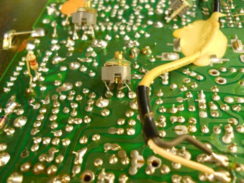
About that 'flush with the rim' tuning slug. What this tells us is that the internal ceramic capacitor in that coil has gone open circuit. If the schematic reveals an internal capacitor for that coil, this is probably what's going on. When the cap goes open, the only way to get back a resonant peak is to add more inductance. The 'flush with the rim' position is the max-inductance position of the tuning slug. But maxing out the coil's inductance won't allow you to reach resonant frequency, only gets you closer than the slug's original position did. Our quick-and-dirty fix for this is to solder a trimmer capacitor across the two solder pads of the coil's pins where the capacitor is wired inside. Typically the outer two pins on the side with three pins. Typically, but not always.
Here's an example that may or may not apply in any way to your radio.
We have found that exposure to high humidity seems to be unhealthy for the internal capacitors in tuneable IF/RF coils/transformers. I'll skip the theory about why, for now.
If the one coil you observed with the 'flush' slug position is in a transmit circuit, this could reduce transmit power. Likewise if found in a receiver circuit, the radio will lose sensitivity to weak signals.
And if it's in a PLL circuit, might affect both.
The older these radios get the more often we see this. One Galaxy Saturn radio that was kept in a damp basement a little too long ended up with seven trimmer caps on the solder side of the pc board. Once that was done, it tuned up and performed like it should.
YMMV.
73
About that 'flush with the rim' tuning slug. What this tells us is that the internal ceramic capacitor in that coil has gone open circuit. If the schematic reveals an internal capacitor for that coil, this is probably what's going on. When the cap goes open, the only way to get back a resonant peak is to add more inductance. The 'flush with the rim' position is the max-inductance position of the tuning slug. But maxing out the coil's inductance won't allow you to reach resonant frequency, only gets you closer than the slug's original position did. Our quick-and-dirty fix for this is to solder a trimmer capacitor across the two solder pads of the coil's pins where the capacitor is wired inside. Typically the outer two pins on the side with three pins. Typically, but not always.
Here's an example that may or may not apply in any way to your radio.
We have found that exposure to high humidity seems to be unhealthy for the internal capacitors in tuneable IF/RF coils/transformers. I'll skip the theory about why, for now.
If the one coil you observed with the 'flush' slug position is in a transmit circuit, this could reduce transmit power. Likewise if found in a receiver circuit, the radio will lose sensitivity to weak signals.
And if it's in a PLL circuit, might affect both.
The older these radios get the more often we see this. One Galaxy Saturn radio that was kept in a damp basement a little too long ended up with seven trimmer caps on the solder side of the pc board. Once that was done, it tuned up and performed like it should.
YMMV.
73
Ivecseen a similar issue with old zenith radios that have a silver sided cap in the can. They oxidize and short out causing smoke to escape. This particular can is located up front inside one of those shield covers. Its on the same side as the output. It may very welk be associated with both rx and tx. I will check the schematic and make a list of the coil cans that are along the path. There are a few small flat green disk caps that come off the collector emitter on the final and on that same bus all the way to the pl259. I am able to check very small caps up to 20uf and down to the pico so i will check all that. I do have new cans but not sure what the windings are or the value of the internal cap. I bet those trimmers work way better than the factory because you can really align them for any variation within the coil from age. Cool.
73s
73s
A
Audio its killer. Ears killer. O just gotta get it transmitting properly. Its not the driver or final. It has to be coming from the TX feed somewhere upstreamThe TRC 448 uses the same Plessey SL1626 chip for audio that the SBE Sidebander V/Console V use. Meaning it should have good audio. May not, but it should.
VSWR,
wha transistors did you use to replace the final and driver and where did you get them from?
looks like this radio used a 2SC1307 final and your chances of getting a real one of those is pretty low.
if you got it on ebay you can be pretty sure its a fake.
the driver looks to be a 2SC2020 which ive never heard of.
what was the actual driver part number that was in the radio originally in yours?
LC
Could be fake. There are 3 different combinations of finals for this radio. 1306, 1307 is 1 combo, another is 2020 and 2098. The 3rd I can't recall.off hand. I have about 100 radios here in the shop. I could pull a set of known working ones from another rig but at this point I think there are other issues with it. The transistors test over 135 hfe and voltages seem ok. If the Chinese can create fake Hfe thats amazing. I know that they did it with ram. I have no respect for anyone making fugazi parts for anything but thats a whole other story. Im going to see what happens if I can get some RF measurements. This radio had a blown 2098 when I got it. Im gonna try a 2078 and see what happens. Im working on multiple radios now. Most problems is over tweaking and messing with calibration not using proper test equipment. Typical CBer bs. Thanks for the help. Appreciated.VSWR,
wha transistors did you use to replace the final and driver and where did you get them from?
looks like this radio used a 2SC1307 final and your chances of getting a real one of those is pretty low.
if you got it on ebay you can be pretty sure its a fake.
the driver looks to be a 2SC2020 which ive never heard of.
what was the actual driver part number that was in the radio originally in yours?
LC
About that 'flush with the rim' tuning slug. What this tells us is that the internal ceramic capacitor in that coil has gone open circuit. If the schematic reveals an internal capacitor for that coil, this is probably what's going on. When the cap goes open, the only way to get back a resonant peak is to add more inductance. The 'flush with the rim' position is the max-inductance position of the tuning slug. But maxing out the coil's inductance won't allow you to reach resonant frequency, only gets you closer than the slug's original position did. Our quick-and-dirty fix for this is to solder a trimmer capacitor across the two solder pads of the coil's pins where the capacitor is wired inside. Typically the outer two pins on the side with three pins. Typically, but not always.
Here's an example that may or may not apply in any way to your radio.
We have found that exposure to high humidity seems to be unhealthy for the internal capacitors in tuneable IF/RF coils/transformers. I'll skip the theory about why, for now.
If the one coil you observed with the 'flush' slug position is in a transmit circuit, this could reduce transmit power. Likewise if found in a receiver circuit, the radio will lose sensitivity to weak signals.
And if it's in a PLL circuit, might affect both.
The older these radios get the more often we see this. One Galaxy Saturn radio that was kept in a damp basement a little too long ended up with seven trimmer caps on the solder side of the pc board. Once that was done, it tuned up and performed like it should.
YMMV.
73
There are 3. Part of the 34mhz AM and SSB oscillator cct. T6, T7,T8. T7 has no inner cap. The other 2 do. Sams doesnt show the values on the schematic and the parts list doesnt show any tuning coils. T7 Feeds T8. There are 2 tuning caps in that circuitry. These culprits are all located under the RF tin covers upfront. A fellow also told me about fake transistors. I knew that could be a possibility but had doubts because of my hfe findings. 150 is dang good gain for a final. How can they fake this? Anyhow, I do have a bunch if different known working ssb rigs that I can temporarily borrow the finals from. Before I do that I will test these possible fakes in the known good sets. If they drop in power well that answers part of the problem. Then I will move the good set to the 448 and see what happens. Stay tuned y'all!Could be fake. There are 3 different combinations of finals for this radio. 1306, 1307 is 1 combo, another is 2020 and 2098. The 3rd I can't recall.off hand. I have about 100 radios here in the shop. I could pull a set of known working ones from another rig but at this point I think there are other issues with it. The transistors test over 135 hfe and voltages seem ok. If the Chinese can create fake Hfe thats amazing. I know that they did it with ram. I have no respect for anyone making fugazi parts for anything but thats a whole other story. Im going to see what happens if I can get some RF measurements. This radio had a blown 2098 when I got it. Im gonna try a 2078 and see what happens. Im working on multiple radios now. Most problems is over tweaking and messing with calibration not using proper test equipment. Typical CBer bs. Thanks for the help. Appreciated.
73s!
dxChat
- No one is chatting at the moment.
-
-
dxBot:63Sprint has left the room.
-
dxBot:kennyjames 0151 has left the room.
-
-