Hello , new here ! This seems to be a very informitive group. I purchased a Silver Streak 150 from a friend. The relay sticks on occasion and the audio is RF'ed ,I am told. I read through many posts on the internet. I tried dropping the radio wattage to 1-2 on am but the relay still hangs on occasion. I tried installing the setup in the mobile - same result. Tried amp with different radio - same result. Tried stock mic - same result. Read that the relay driver transistor may be leaking causing this problem. Which is the driver trans? I can solder and desolder. Read that the coax jumpers may be at fault. Reduced them and still same. (This happens on ssb and am). Antenna system is new. SWR is nearly perfect. Thanks for any help ...

You are using an out of date browser. It may not display this or other websites correctly.
You should upgrade or use an alternative browser.
You should upgrade or use an alternative browser.
-
You can now help support WorldwideDX when you shop on Amazon at no additional cost to you! Simply follow this Shop on Amazon link first and a portion of any purchase is sent to WorldwideDX to help with site costs.
Relay sticks in linear
- Thread starter unit511
- Start date
The relay in that is a 3 legged part so if thats the problem you will need a new one. That said try a 6 or 9 foot jumper and see if that helps. That and make sure you have good grounds and a properly set-up antenna system. Silver Streak amps are cool little amps.
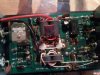
The tin can circles is the keying circuit transistor and is most likely the culprit the other circled is the sensing capacitor for the keying circuit and you could changed that if you have to use too much power to make the amp key up.Hello , new here ! This seems to be a very informitive group. I purchased a Silver Streak 150 from a friend. The relay sticks on occasion and the audio is RF'ed ,I am told. I read through many posts on the internet. I tried dropping the radio wattage to 1-2 on am but the relay still hangs on occasion. I tried installing the setup in the mobile - same result. Tried amp with different radio - same result. Tried stock mic - same result. Read that the relay driver transistor may be leaking causing this problem. Which is the driver trans? I can solder and desolder. Read that the coax jumpers may be at fault. Reduced them and still same. (This happens on ssb and am). Antenna system is new. SWR is nearly perfect. Thanks for any help ...
I didn't circle the diodle from the key transistor to ground but it's the little orange and black part directly left of the tin can, you should lift one end of it and check and if it shows continuity in both directions it will have to be replaced.
bao
Doing this job will be a good little task for you, start by desoldering the pl-259 connectors where they enter the back then the +/- power leads from the board and then remove the nut holding the switches at the front of the cabinet and then the 4 phillips head screws that hold the power transistors to the heat sink and you should be able to remove the entire circuit board from the case.
Remember to clean the faces of the power transistor and heat sink where they contact and to apply one small bit of new heat sink compound that you can purchase at radio shack if you don't have any and spread that evenly on the face of the transistors(not too much compound, just enough to make a thin coat) and then reverse the assembly order.

Last edited:
Nice Informative Reply
Thanks for a great pic showing transistor. I have 2 transistors in my unit. I think one is for receive amplification. Its a 2n3906. The one you have circled is a 2n2907a. Indicator lamps are to be popped out of sockets? Can I not just drop the heat sink from the bottom by removing screws from pills and 2 screws in front plate and 2 screws in back plate? Also a couple holding down PCB.
Thanks for a great pic showing transistor. I have 2 transistors in my unit. I think one is for receive amplification. Its a 2n3906. The one you have circled is a 2n2907a. Indicator lamps are to be popped out of sockets? Can I not just drop the heat sink from the bottom by removing screws from pills and 2 screws in front plate and 2 screws in back plate? Also a couple holding down PCB.
Last edited:
Thanks for a great pic showing transistor. I have 2 transistors in my unit. I think one is for receive amplification. Its a 2n3906. The one you have circled is a 2n2907a. Indicator lamps are to be popped out of sockets? Can I not just drop the heat sink from the bottom by removing screws from pills and 2 screws in front plate and 2 screws in back plate?
I wasn't exactly sure of the construction but you have it in front of you so if it would work your way best then yes.
Pictures welcome.
There are some differences between these units. Should I be concerned? The capacitor you wrote about is a z5v 50v. What cap do i use for higher power drive from radio?
When you raise the value to a higher value you change the input drive to a higher wattage which may not be good for the output of the amp.
Keeping it OEM
Ok I will not touch the cap but I have ordered new motorola gold lead 2n2907a's. Could i not just snip the long lead off the transistor and solder the new to the stubs? This way i don't need to mess with any other pieces that may break or bend? Is this too rube goldberg? Wouldn't the metal can of the 2n2907a direct rf to ground? Sorry... i'm learning.....
Ok I will not touch the cap but I have ordered new motorola gold lead 2n2907a's. Could i not just snip the long lead off the transistor and solder the new to the stubs? This way i don't need to mess with any other pieces that may break or bend? Is this too rube goldberg? Wouldn't the metal can of the 2n2907a direct rf to ground? Sorry... i'm learning.....
Ok I will not touch the cap but I have ordered new motorola gold lead 2n2907a's. Could i not just snip the long lead off the transistor and solder the new to the stubs? This way i don't need to mess with any other pieces that may break or bend? Is this too rube goldberg? Wouldn't the metal can of the 2n2907a direct rf to ground? Sorry... i'm learning.....
You said 'Rube Goldberg' . . . That's funny . . .
The problem with soldering a transistor with really short leads, is that the heat buildup in the transistor might become too much and damage it. One way around this dilemma is to attach an alligator clip on one lead on the transistor at a time so that it will absorb the excess heat. Otherwise, I would just turn the board over and replace it as it should be. Using a pencil soldering iron of 25-40 watts ONLY!
What he said
Well I received the transistors - 4 for 5.99 shipped fron Arizonia. Replaced it by cutting the old one at the can , which left me stubs about 3/8 inch to solder the new one to. I tinned the ends of the stubs and of the new trans. I then matched up the polarity and hit the legs with the solder gun and bingo ----done. Buttoned up the unit, installed inline, powered up, and bingo--- works great!!!!!!No more relay sticking and no more rf in my audio......Spoke to Houston Texas area...audio great!!!!NICE. Thanks out to mackmobile43 for the great pic and instructions. I am happy again......Now I have to find away to cool the amp down because I talk too much.....Thanks for all the help.
dxChat
- No one is chatting at the moment.
-
-
-
@ BJ radionut:
Discord - A New Way to Chat with Friends & Communities
Discord is the easiest way to communicate over voice, video, and text. Chat, hang out, and stay close with your friends and communities.discord.com
-
-
