• You can now help support WorldwideDX when you shop on Amazon at no additional cost to you! Simply follow this Shop on Amazon link first and a portion of any purchase is sent to WorldwideDX to help with site costs.

RF LNA on a budget

Cable Guy

Void where prohibited
Dec 29, 2010
299
244
53
West Tennessee
If you have issues getting your >20mv scope to trigger on <20mv signals, or the 1x probe loads down the circuit causing random inaccurate readings/stalling, check this out.
Screenshot_20240108-102311.png

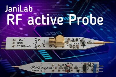
I saw a video on YT about this device, using it as a RF preamp and as an amp for your probes. The gain is variable, depending on voltage applied from about 3v to 12v. I know it says 9-12v but it does work at 3v with reduced gain. It comes with sma connectors so you can use bnc adapters if needed, I chose to replace them with bnc instead.
IMG_20240108_095218292.jpg
IMG_20240108_095154087.jpg

And install into the Altoids tin.
IMG_20240108_095305247.jpg

IMG_20240108_095350027.jpg

I don't have any hard specs but now I can read <20mv signals on the FC with a 10x probe and no bouncing. I could add a variable voltage regulator for adjustable gain, and I may do that someday, but the straight 9v offers plenty of gain for anything I need at the moment.

I wish I had known this years ago.
IMG_20240108_095325420.jpg


73s
Greg
 

I saw a video like that a while back and bought 3 different amplifier modules. My reaction, at first, was the same as yours. Here's where I ran into trouble.

The modules have a 50Ω input impedance, so in 1x mode, the 1MΩ input impedance typical of frequency counters and scopes is now parallel with the probe cable capacitance and 50Ω. This means the impedance at the probe tip is now under 50Ω instead of ~1MΩ (plus cable capacitance) and will be nearly useless for probing any high-z signals. Even though the amplifier is making the signal bigger, the circuit is being loaded down so much more that the signal at the probe tip is destroyed or circuits stop oscillating.

In 10x mode, You have a much better situation for the circuit under test as it is isolated from the probe cable capacitance and the 50Ω amplifier input by that internal 9MΩ resistance. But now, instead of a 9MΩ/1MΩ divider (signal volts/10), you have a 9MΩ/50Ω divider. Now the amplifier input is only seeing 1/180,000 of the signal voltage instead of 1/10 of it. With 30dB gain, you still get a usable signal out (not always the case with a 20dB amp, as I found out), but now any tiny bit of noise that gets into the probe through the cable shield/ground can become a real problem. For example, you might find that one day this works fine and the next your FC is bouncing all over the place. If this happens, check ground connection and keep your arm holding the probe away from metal (desks, radio chassis, etc) that may have stray 60Hz AC or RFI.

The ideal solution is to have an active probe, something with a high z input / low z output amplifier at the probe tip driving the cable. If designed with 0dB gain, you get to see what the circuit voltage is without loading it down.

In any case, regardless of whether you stick with that in-line amp or dabble with the best active probes money/time can buy, when it comes to SSB rigs, the probe will still change the frequency of an oscillator. I recommend setting a signal generator to produce a tone in the radio's receive and monitor that with an audio spectrum app while you probe the oscillators. The added capacitance from the probe will cause a shift in the tone and the app will tell you how much. In most radios, the oscillators will respond to the added capacitance by decreasing frequency, so whatever difference you get in the audio tone when probing is the number you should subtract to your readings when you do a frequency alignment on that test point. Edit: the tone change in the RX could go either way because mixer outputs can be taken as differences instead of sums, so it could move the other way. But most crystal oscillators respond to more capacitance by a lowering of the frequency. The BF998 DIY active probe I made will pull an oscillator 10-20Hz and that alone gobbles up the allowable alignment tolerance. My point is don't trust the readings just because they are amplified and stable.
 
Last edited:
Thanks for sharing your experience, I also noted that when the probe is not connected to anything, it picks up whatever and amplifies. Nothing is perfect as you already know, and I may not get the greatest accuracy but I can get close enough for my satisfaction, knowing the limitations and operating within. Wonder what the input impedance is on that amp? Anyways I'm always learning and look forward to, and value, y'all's morsels of knowledge. One day, I will be confident. I'm going to check out that spectrum app you mention. For ssb I usually use my ears to tune with a tone, similar to tuning a guitar with harmonics, you can really hear the offset, zero beat it down darn close, enough that no one ever tells me I'm off frequency.
 
After re-reading your post, I see what you're getting at, regarding the insertion of the amp between probe impedance/resistance and the divider formed with 1M input to the FC, no longer following assumed standard formula, as if the amp wasn't there. All that acting up on the fragile circuit. I've got some more thinking (and reading) to do over here, if I am going to be on that level. That "every action, equal opposite reaction" thing.
 
  • Like
Reactions: tecnicoloco
That's almost identical to the one I built, but it is worth noting that, as-is, that one has it's output -20dB down from the signal at the probe tip. That means if you build this and probe a signal at 500mV, what the FC sees is only at 50mV. Suddenly you are right back down where the FC wants to stop counting. I recommend connecting a signal generator to your FC and see exactly where it gets unstable, its a good number to be aware of. At least the output of that active probe is 50Ω and could be connected to the amp he already built (and get +12dB out). Edit(math error): so with a 500mV signal, you get 2v to the FC with that amp.

This write-up of the project talks about that gain issue.
 
Last edited:
You can buy one ready to be stuffed into a housing for $30. I remember when that active probe plan first dropped, there were a dozen people selling them and they were only $20. That didn't last long. I had a hard time finding that one.


I was wrong, they are still online for $12, just search for RF active probe. I searched for BF998 probe and got less results.
 
Hi Brandon

Thank you for your answer,orientation and observation

I really appreciate for sharing your knowledge


Regards
Andy/Tecnicoloco
You're welcome! I know I get long-winded sometimes, just trying to spare the next person from the misery I went through. When I first got my FC, I thought I had the game whooped. Then i realized I couldn't get a reading on half the test points. Saw the amp module video, got some amplifiers ordered and felt better until 20% of what I probed at still gave unstable readings. I gave up on non-active probes and made the BF998 probe and went back to feeling like I had life by the balls, just to later discover (because I didn't read it, just took the schematic) that the gain is -20dB due to the capacitive divider at the input and once again my forehead found its usual resting place by my keyboard. Been a bumpy road with lots of wasted time and wasted parts.
 
@brandon7861
I just received the probes, but they have a strange connector on them. Looks like a push on, but my push on isn't exactly the right size, a little too small. Would you know what connector it is?
17061219524867686600980954504711.jpg1706122018272864108007080971804.jpg

Also, this thing is tiny. I'm searching for a suitable enclosure. Do you think I should change that connector for something else?
 
@brandon7861
I just received the probes, but they have a strange connector on them. Looks like a push on, but my push on isn't exactly the right size, a little too small. Would you know what connector it is?

Also, this thing is tiny. I'm searching for a suitable enclosure. Do you think I should change that connector for something else?
I'm guessing those are MCX connectors. I think the connector you are looking for fits inside that one rather than over it.

I put the one I built in a piece of copper pipe and used two pipe caps with holes drilled in them for the ends.
 
  • Like
Reactions: Cable Guy
Thanks for that, I see the mcx male end would be what I need. I should have one by Friday so that gives me time to work on the enclosure. I think I have the copper pipe already so, off to the workshop I go. Then to work on a power supply for it. I'm new to active probes and you have been most helpful. I see a RF DC out pin on the probe, is that just a rectified rf output? What would that be good for? I may have more questions later, assuming I'm not wearing the welcome out.
 
It might be worth removing the connector and going straight in with some coax. Fitting an adapter inside a tube with that board in the center of the housing tube will mean a larger than ideal diameter. I recently got some RG178 off amazon for my probe and I really like it. Its diameter is about that of pencil graphite and quite flexible. Having a heavy coax coming off the probe is a pain.

I would guess (based on the diodes on the back of the board) that RF DC out is is rectified RF. If you feed that into an audio amp, you should be able to hear the AM modulation of an RF signal which is a really nice for troubleshooting IF stages.

Edit: Calling that pin RF DC out instead of mod or audio out suggests that there may be a DC offset. Although it appears that C2 (from their low resolution image on the website) is in line with that pin, I cannot see the traces and cannot guarantee that. I assume it is decoupled audio, but its best to be sure before connecting things to it.
 
Last edited:
  • Like
Reactions: Cable Guy
I have some rg316 I need to find a use for, it's kinda thin and sorta flexible. I can terminate it with bnc at the end of the enclosure or I could wire it direct into the amp. Couldn't the RF DC output be used as a relative signal strength into a volt meter?
 

dxChat
Help Users
  • No one is chatting at the moment.