• You can now help support WorldwideDX when you shop on Amazon at no additional cost to you! Simply follow this Shop on Amazon link first and a portion of any purchase is sent to WorldwideDX to help with site costs.

RFX95HD only seeing 50w peak

Hawkeye351

Well-Known Member
Jun 27, 2021
511
387
73
56
Just got finished installing a brand new RFX95HD on a Cobra 29 LTD Classic.

The radio alone swings up to 22w peak, and forward 1w on average from any key level (it had variable installed with a Tip120). The RFX doesn't seem to like the variable key, but everyone said it sounds awesome all the way up, which yields a 12w deadkey and swings to 50w, slightly over a 4:1 ratio. After installing the RFX95HD, all it'll do is 50w peak. I've never gotten any of these RFX amps to show more than 60w peak on my meter and scope.

I think I know why now.
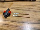
The power cable I use on all these mobiles, regardless of what radio I'm working on, is the standard 3 pin 2 wire red/black wire that comes with cobras. I think it's only rated at like 4A and 15w up to 25w peak output power.

If this is the case, then that would explain meter lights dimming on these radios when I modulate over 35w on any radio I'm working on, and the struggle to see anything steady over 50+ watts peak.

My 949 w/RFX75 mounted on the back that I normally run in my truck runs the same power wire, and it never shows over 50w peak and the meter light dims with modulation, not severely but it does dim.

What power cable do you guys recommend be used for these RFX installs? Or am I wrong in blaming the power cable being underrated?

Probably a dumb question, but felt the need to ask the experts out here
 

I ran 8ga when I had my 203 (100w) Still use that wire for my 503.

Anyway your radio should pull 100w. I think you need bigger wire. Also…are you checking power levels with your vehicle off?? That’s also going to make a difference. Hope this helps!!
 
  • Like
Reactions: Hawkeye351
Thank you shadetree and forestrunner for chiming in.

Shadetree, that's some nice looking work.

Forestrunner, with the truck running and not running, power output is still 50w peak max.

Even on my 35A power supply on my desk, power output is still only 50w peak max.

I run the same cheap 4A wire on both my truck and my desk power supply.

Been hammering on it in my truck for the last hour and everyone said the carrier is strong and steady, modulation is awesome for a stock mic. Amp got hot but not scorching hot after an hour of long winded talking, cools back down smoothly. No issues, other than only 50w max output.

Double checked my alignment, especially the VCO voltage and both VCO Buffers. Signal on the spectrum looks typical for these RFX amps. Final and driver in the radio itself stays cool to warm.

I'm tapping my +8v transmit only from JP29.

Power supply amperage meter shows about 6.5A with a deadkey of 12w and climbs up to around 10.5A when modulated. Fuse does get pretty warm, but not hot when modulated. Wire is flimsy thin stock power wire.

Could the standard 4A power wire really cause this much power loss?
 
Last edited:
There's a thread here where a few of us installed those on radios. With the stock power cord and plug I did see right under a hun on my meter but there was some extreme current drop with dimming as you mention. I upgraded the plug, wire going to the main pcb, and used the workman heavy duty cord. Still around a hundred but less current drop and light dimming. I'll look for that thread.
 
 
  • Like
Reactions: Hawkeye351
If your running 4g wire then it should be good. Wait…does your power meter read PEP as well as average power??? If it doesn’t the 50w is average power and PEP is….100?
MFJ 872 watt meter.
It has a PEP/AVG switch.
5w/20w/200w scales.

I don't think it's 4g wire, although it does have a marking on the wire that's says 4A. Probably 14g wire.

I also have the big window 2000w MFJ 868 meter with Peak/Avg scale. Hardly ever use that one.

I also have a used Dosey TC4001 watt meter with Peak/Rms scale. Haven't used it cause I'm unsure if it's been tinkered with.

Just came back in after hammering on it in my truck again. Still same output, everyone says the signal is still strong and holding steady, modulation still banging for a stock mic. Runs great with the RFX, no issues other than dimming meter light and can't see that 100w out of it, only 50w max.

No other mods done to radio except variable key off the RF Gain control through the Tip120 with the cap/resistor swing mod at JP36.

Same output as my RFX75 on my 949, only 50w max.

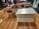
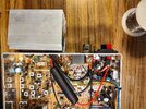
This is how I got it hooked up in the 29:
1. Antenna wire on so239 removed from so239 and board.
2. RF output wire (red) center wire to so239 center pin.
3. RF input wire (white) center wire to vacant hole where so239 Wire went on the board.
4. Both input and output shields tied together, then soldered to metal flange on so239 for ground, had to add a short piece to reach.
5. Red and black wires tied into DC input jack on back of radio.
6. The +8v wire soldered to JP29.

SWR meter on radio shows a 2 on SWR with amp installed and running.
 
MFJ 872 watt meter.
It has a PEP/AVG switch.
5w/20w/200w scales.

I don't think it's 4g wire, although it does have a marking on the wire that's says 4A. Probably 14g wire.

I also have the big window 2000w MFJ 868 meter with Peak/Avg scale. Hardly ever use that one.

I also have a used Dosey TC4001 watt meter with Peak/Rms scale. Haven't used it cause I'm unsure if it's been tinkered with.

Just came back in after hammering on it in my truck again. Still same output, everyone says the signal is still strong and holding steady, modulation still banging for a stock mic. Runs great with the RFX, no issues other than dimming meter light and can't see that 100w out of it, only 50w max.

No other mods done to radio except variable key off the RF Gain control through the Tip120 with the cap/resistor swing mod.

Same output as my RFX75 on my 949, only 50w max.

This is how I got it hooked up in the 29:
1. Antenna wire on so239 removed from so239 and board.
2. RF output wire (red) center wire to so239 center pin.
3. RF input wire (white) center wire to vacant hole where so239 Wire went on the board.
4. Both input and output shields tied together, then soldered to metal flange on so239 for ground, had to add a short piece to reach.
5. Red and black wires tied into DC input jack on back of radio.
6. The +8v wire soldered to JP29.

SWR meter on radio shows a 2 on SWR with amp installed and running.
If I remember correctly, @Shadetree Mechanic had to adjust the amp bias pot to zero his in. Be cautious though, a little too crazy and the 9530 will puff out the magic smoke.
 
Hahahaha, 4awg, 1awg, etc completely unnecessary and overkill. 12awg is big enough and more than sufficient to carry the current draw of a 100w transmitter with no problem at all.
 
  • Like
Reactions: Hawkeye351
So I should adjust the bias VR on the amp to lower the SWR to "0" or closer to "0", or adjust it for amperage draw on my power supply amperage meter?
 

dxChat
Help Users
  • No one is chatting at the moment.