• You can now help support WorldwideDX when you shop on Amazon at no additional cost to you! Simply follow this Shop on Amazon link first and a portion of any purchase is sent to WorldwideDX to help with site costs.

Strange arc welder sound in a new PC68LTX TX audio

brandon7861

Loose Wire
Nov 28, 2018
1,157
1,262
193
Talking to a local friend while he was testing out his one week old Uniden PC 68LTX and there is a strange sound that briefly occurs when he keys up. It wasn't there a few days ago when I first heard him on it. I had him switch radios and it went away. Looking at the audio recording from my phone, there are 4 or 5 pulses at 60Hz, and if I bandpass filter it, I can see that those 4 pulses have a brief 333Hz component to them. He has a 2 year warranty, but I am not sure the problem is in the radio. The power supply he is using does not do this on other radios, but that doesn't really mean anything as his other radios are different. I will admit, I had my hands in that PS a few years ago. It had been cooked and butchered and I ended up putting a new 2N3055 in it and used an LM317 to set the base voltage. It had no ripple then and seems to work fine on other radios, but then again, this is 60Hz noise. It is almost like the RF amp is amplifying power line noise before the TX signal has time to get to the amplifier, and once it does, the noise goes away. Could this be somehow coupling into the radio through the antenna or coax braid and being amplified by the drive/final? Hoping someone has seen this before.
uniden noise.png

uniden AM 2.png
 

Attachments

  • uniden noise.wav
    760.6 KB
Last edited:

He brought a battery in the house, still does it. Not the PS.

Edit: He also said he has a lot of noise on any radio without the noise blanker on. So there is strong power line noise and that it must be getting into the radio via the antenna somehow, but I never seen a radio do this on TX before.

Edit2: I don't have a schematic, but since it is a AM only radio, is it possible that the radio uses base-leak/self-bias and as the incoming RF starts to bias the driver, but before that bias raises sufficiently, that the impulse noise from the power line is momentarily turning it on harder? The problem only exists for the first 1/15 of a second after he keys up.
 
Last edited:
To my ears it sounds like settling noise from the radio's PLL. If I'm right, it will be much louder if you select FM on the receiver you monitor it with.

The PLL in that radio "jumps" 455 kHz when you transmit. The PLL is supposed to lock onto the new frequency pretty much right away when you key the mike. Something is making the PLL a bit lazy to lock in.

If I'm right.

Listen to it in FM and see if that makes the noise louder.

73
Thank you. I will hook up an FM radio and have him give it another try.

Update: He seems to have fallen asleep at the mic. Tomorrow then. Thanks!!
 
Last edited:
I woke him up lol. On FM, it seems to just goes silent when he keys. Maybe I can still hear it a little, but it doesn't seem as bad. This radio does need an alignment It was harder to hear it in AM on this radio.
uniden noise 2.png
FM zoomed in.png
 

Attachments

  • uniden noise 2.wav
    1.2 MB
I tried doing the same thing in SSB with my clarifier arbitrarily turned to produce a an audible tone from his dead key and recorded that audio.

It doesn't just look like it is taking time to settle, it looks like it is having a hard time deciding where to be and oscillating between two states. Could it be switching noise on that PLL pin or maybe on a crystal oscillator bias???. It is only shifting by around 500Hz-600Hz, not 455kHz.

I wish I could scope that pin quick..
uniden ssb 1.png
 
Last edited:
As a rule, faults caused by an unstable PLL are all loudest when listening to them with an FM receiver. If you only hear this noise in AM, that points away from the PLL. I would suggest putting the scope probe onto the radio's switched regulated transmit-only power supply voltage, and onto the receive-only side. See if any of this noise appears there. Should be a flat DC trace, clean as the driven snow. More to the point, if the receive side fails to fall all the way to zero Volts while transmitting, this can create all manner of hard-to-explain noises.

73
 
  • Like
Reactions: brandon7861
As a rule, faults caused by an unstable PLL are all loudest when listening to them with an FM receiver. If you only hear this noise in AM, that points away from the PLL. I would suggest putting the scope probe onto the radio's switched regulated transmit-only power supply voltage, and onto the receive-only side. See if any of this noise appears there. Should be a flat DC trace, clean as the driven snow. More to the point, if the receive side fails to fall all the way to zero Volts while transmitting, this can create all manner of hard-to-explain noises.

73
I may have to bring it home the next time I go past his place. I wonder what these new radios have for tamper stickers and if poking around inside will void his warranty. I know if he sends it in, they will say nothing is wrong and it will be shipping wasted, but if I open it up and void the warranty just for something else to act up later, then I will have volunteered myself for a job I may not want. Not sure what to recommend to him at this point.
 
Seems to me it was EEVblog on YouTube that showed how to defeat a tamper-proof label.

Maybe? Seems to me it involved a razor blade.

73
I saw that. Not that confident I could do a convincing job. No practice stickers here

edit: I lied, just realized my siglent has a sticker and that warranty should be long over by now. I will have to give it a try.
 
Last edited:
Good news, no sticker on the radio. Even better news, he don't care about the warranty. Bad news is that I brought it home and now I have to look at it. That's a project for tomorrow. Meanwhile, I just played my first game of battleship over the air, lasted longer than I expected it to!
 
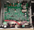
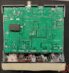
I was joking about having to figure this out being "bad news" lol, I do love this stuff... Anyhow, here's a quick update with some board pictures.

Since trying to figure out how it keys includes figuring out the synthesis, I will go over what I know so far about that.

This radio uses the BU2630F PLL (which is being discontinued by the manufacturer already). It is a dual PLL, but this particular radio is only using one side of it. The other side of the PLL is mostly unpopulated pads and I assume they are for FM circuitry this model doesn't offer. There are two crystals, but only one is being used for synthesis, the other is serving as a filter.

On RX, the PLL is causing the VCO (Q304) to output 16.43MHz (on ch 14) which mixes with the 27MHz incoming signal to generate a 10.695MHz IF, which is then mixed with the 10.240MHz signal to provide the 455kHz signal for the ceramic filter.

On TX, the same side of the PLL is outputting (again, ch 14) 16.885MHz which mixes with the 10.24MHz to generate the 27.125MHz output.

The downside of using just one side of this particular PLL is that the frequency change needs to be clocked in each time the radio is keyed and unkeyed. Looking at the output waveform, there is clearly a frequency shift in the first few ms of transmission (you were right @nomadradio). Without a delay added somewhere to let it settle before transmitting, I fear there is little I can do.

With the assumption that I cannot change that delay without serious alterations, I am moving on to learning what I can about the radio while I have it here. My next step is to add wires to the clock and data lines so I can see exactly what the micro is saying to it. I already probed the data input, but without triggering on the clock and using two probes, that data is useless to me because it is not referenced to the clock pulses. In other words, I didn't have three hands. Thankfully, the owner gave me the green light to add a wire to the clock and data to free up my hands so I can see both while I turn knobs and key the radio.

Interestingly, the unused side of the PLL is outputting 27.125 on TX, so the other side of the PLL has apparently received some data for FM synthesis (which hasn't been populated on this board). I think I know what to expect from the datasheet, so I am hoping to see all of that on the scope when I turn on the radio.

I don't know much about the rest of this radio, but I think the PLL has a lot to offer if combined with an arduino (too bad it isn't my radio). Even the reference oscillator chain has a programmable divider, so any step you want can be programmed in. Super wide range, lots of capability there. IMO, Uniden under-utilized this PLL in the cheapest possible fashion.
 

Attachments

  • IMG_20240106_172830624.jpg
    IMG_20240106_172830624.jpg
    4.6 MB · Views: 25
  • IMG_20240106_172423904.jpg
    IMG_20240106_172423904.jpg
    3.5 MB · Views: 23
  • Like
Reactions: Cable Guy and TM86
Got the data figured out. Just like the datasheet says too.

The datasheet makes it a bit confusing with the use of "TX" and "RX" for the two sides of the PLL (should be called side A and side B or something else). This radio only uses the "TX" side of this PLL for both TX and RX by clocking in the offset freq divider data each time the key is pressed or released. I will break this down for nayone that wants to do a channel mod (with a micro).

When the radio is powered, the channel is changed, or the PTT button is pressed/released, two data sequences are sent to the PLL with a 2ms delay between them (although I don't think that delay is critical). The first burst represents the reference divider data and the second burst represents the VCO divider data. With the radio on ch1, lets look at that.
ch1 PLL data.png


The first burst is the reference divider (blue=clock, red=data).
ch1 reference divider data.png

Here, the leftmost 14 bits are the divider data and the remaining 10 are control data (that last bit on the end signifying its for the reference divider). The first 14 bits are binary representing hex chunks clocked in backwards, so 0000 0000 0001 00XX XXXX XXXX translates to 00 1000 0000 0000, which in hex is 0800, which in decimal is 2048. 10.24Mz/2048=5kHz. The PLL phase detector uses 5kHz. This does not change with TX/RX or channel.

Next is the VCO divider data. Looking at TX first. When the key is pressed, the second burst looks like this:
ch1 VCO divider data tx.png

With the VCO divider data, the first 16 bits are taken. 1000 1000 1011 0000 XXXX XXXX, which written the other way around is 0000 1101 0001 0001, which is 11D0 in HEX, which is 3345 in DEC. 5kHz * 3345 = 16.725MHz. When that is mixed (added) with 10.24MHz, the output at 26.965MHz is obtained.

Looking at the burst going back into RX, we get this:
ch1 VCO divider data rx.png

Now the VCO divider is getting 0110 1101 0011 0000 XXXX XXXX, and converting that to HEX we get 0CB6, which in DEC is 3254. 5kHz * 3254 = 16.27MHz, and that, when added to 10.24MHz is 26.51MHz. 26.965 - 26.510 = 455kHz for filtering and detection.

Now you know what to do if you want to arduino extra channels into the radio. Simply interrupt the clock, data and enable signals with your own data with the RX offset triggered on the PTT button. Its edge triggered, so clock frequency is not important. Could probably do it with a set of switches like on Halt and Catch Fire lol (I misremembered scene, just watched it, they manually read a memory chip, they didn't write to one with physical button switches like I thought. Good show though.).

Looks like the days of locked-down PLL's are over, this thing is wide open and capable of more than the rest of the radio could ever imagine :)
 
Last edited:
  • Wow
Reactions: Cable Guy
Edit: the 980SSB uses this PLL, I bet most of the new uniden/president radios do

Edit 2: back to the point.. I noticed the datasheet explains the reference divider sequence after the VCO divider sequence, but the radio sends them the other way around, so I wonder if both even need to be clocked in each time. If there was a way to reprogram the micro to not resend the reference divider burst each time, the PLL could get the new VCO data faster and settle faster.
 
Last edited:
  • Like
Reactions: TM86 and Cable Guy
Brandon, I feel like I just watched some pll porn, looking into the secret, private parts of the thing, that we all knew it had, but never saw it doing it like that before. I feel dirty now, knowing how that pll gets on-and off- to make us happy. Perhaps this is porn for tech nerds. I'll see myself out...
 
  • Haha
Reactions: brandon7861

dxChat
Help Users
  • No one is chatting at the moment.