
You are using an out of date browser. It may not display this or other websites correctly.
You should upgrade or use an alternative browser.
You should upgrade or use an alternative browser.
-
You can now help support WorldwideDX when you shop on Amazon at no additional cost to you! Simply follow this Shop on Amazon link first and a portion of any purchase is sent to WorldwideDX to help with site costs.
2995dx modulation on a scope
- Thread starter GnG8d
- Start date
While on the subject; just what IS the proper NPC mod for this chassis?
Schematic attached . . .
:tongue:
lol..... Its all going to depend on who you talk to!
This chassis is electronically the same as any Galaxy, Ranger, Connex, Magnum .....ect. All the NPC mods are all the same between the export chassis, If you look at the modulator section on all of the above radios there identical. There are a few odd ball radio each company has produced but the majority (%95) of them are the same.
I put a diode in series with R292 and disable the mod limiter on the AM side. Then if the modulation looks like it 359's picture I change the value of R292 to get the negative peaks to %95.
I also do a TX alignment for peak power.
If you look directly above R292 is C258, some people remove C258 and install a diode and 100 ohm resistor in series. They also reinstall the capacitor out of C258 across R292. Some people say that's the right way, but it is the same mod just with more soldering.
There also is a second mod that some people do, they install a diode in series with R290. I usually don't use this mod but it does work about the same as the mod above. Also with using R290 the R292 resistor still has the same effect on the negative peaks, so you can still adjust it if needed.
If I was 359 I would install or have someone install a 5K 15-turn trim pot in place of R292 with the diode in series, so that way its at least adjustable.
Also as 359 noticed when he lowered his carrier the negative peaks got closer to %100, thats why I think the 5K 15-turn trim pot is better. If you decide to change your carrier by more than 5 watts you can still adjust your negative peaks without picking up the soldering iron.
Im not going to tell you what mods better because there is always someone that will say otherwise!
Hope this helps Robb!
Is there a way to do this mod without being so aggressive? I'd either like to rip it out, or at least be able to run a decent sized carrier.
No, you have to remove R292 and install a non surface mount resistor and diode in series.
I have a WES51 with a really fine tip, just a split second on the leg should free it up. I'm fearin not even being able to hit 100% modulation when I'm done359, if you want to remove the diode put your soldering iron on the legs of the diode (not the board) and gently pull the diode off the board when the solder melts.
Or just clip the damn thing!

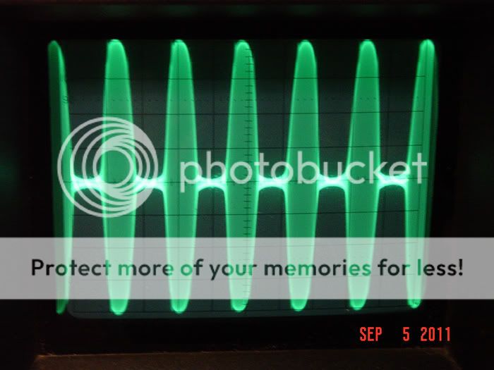
Well I couldn't do it, I had to tear into the 2970 before I went to bed since it was out of line and easy to get to. After removing one leg of the diode, I couldn't get squat out of it without overmodulating badly. I had the AF power anywhere from 40-75w and carrier anywhere from 10-50w and modulation pot full lock both ways. It looked best on the scope at 50w carrier and 125w pep TBH.
I put the diode back in place and I'm getting full out @225pep again so I didn't fry anything anyway, damn I wish I would have torn into some of the older radio's I've had laying around before ripping into a brand new 2970n2 and 2995dx :blink:
I put the diode back in place and I'm getting full out @225pep again so I didn't fry anything anyway, damn I wish I would have torn into some of the older radio's I've had laying around before ripping into a brand new 2970n2 and 2995dx :blink:
359 - you'll love that lighted magnifying lens.
I got mine at Staples for about $40. Uses 90 VERY bright LEDs.
I got mine at Staples for about $40. Uses 90 VERY bright LEDs.
Well the guy who did the work on these radios when I bought them 6 months ago is not responding to my emails. I've bought a half a dozen new radios from him, plus countless dollars in other work and I guess he's not happy that I opened these radios, so I don't know. I never asked for an NPC mod, but I didn't say not to either, so I'm not upset, just a little surprised.
Either way, I decided to investigate a little further while my parts are in transit and R301 is in tact, but Q43 has been tampered with. It looks like the base was lifted, and then soldered back into place. I noticed that the diode across R292 allowed me to use VR17, but with the diode removed it didn't seem to function. Or it did, but just wouldn't allow me to keep it from clipping negative peaks.
So is it possible to clamp negative peaks to 95% while going positive 100% plus with this mod? I really have no desire to key 1w and swing 200w, but a little asymmetry would be nice. I've read to add a diode/resistor combo in parallel with R292, and also to remove R292 and put a diode/resistor combo in it's place. I think I have enough parts coming to try both, including a couple trimmers and SMT resistors. Once I get the 2970 where I like it, I'll just duplicate it on the 2995.
This mod has confused me since day one because I see no filtering being used whatsoever after the clipping takes place. This is evident by the fact the positive peaks are much more rounded then the clipped off negative peaks. I can clearly see corners going into and out of the negative peaks. This effect would only get worse as more compression or gain is added. Every clean and effective form of audio compression I have ever seen always follows the limiting stage with several poles of hi frequency AF filtering after the clipping. Otherwise your just passing the same basic clipped waveform onto the modulator as you would without the mod. The only differences I see are that the added clipping would cause this distortion to occur at lower modulation levels and the RF carrier never reaches cutoff. Proper NPC has much less to do with actual RF cutoff then it does with proper filtering to reshape the clipped waveform.
The people who swear by this mod claim no negative peak clipping is going on, only negative peak compression. I've read so many threads on so many forums and followed so many links in the last 2 days, my eyes are bleeding, but I tend to agree and negative peak compression is nothing new.
My problem with the mod is having to run the carrier so low. I don't want 10w peaking 200, I want 40w peaking 200 with asymmetrical modulation. I don't ask for much though :laugh:
My problem with the mod is having to run the carrier so low. I don't want 10w peaking 200, I want 40w peaking 200 with asymmetrical modulation. I don't ask for much though :laugh:
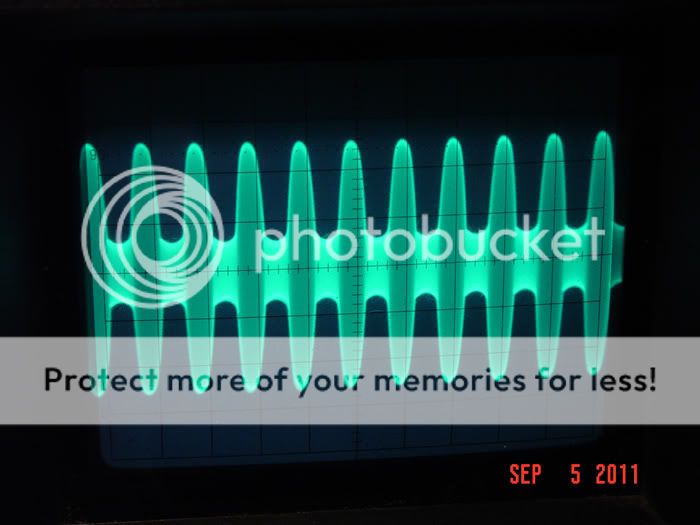
It would seem to me that the people who swear by this mod do not understand the difference between clipping and compression. This mod is absolutely more of a clipper then a compressor. Compression requires clipping with increased gain and filtering after the clipping. All we have here is negative peak clipping. In fact the hams that use a similar 3 diode mod know the circuit sucks at compression and only use it as a sort of back up limiter. Claiming it should not be driven hard into clipping regularly due to the inability to filter out the sharp corners that the clipping action creates.
In order to increase the average modulation level we need more then clipping. We need compression to reduce the dynamic range of the audio signal. To achieve compression we add extra gain so that the peaks are clipped while the lower levels of the modulated waveform benefit from the added gain. This added gain with the clipping of the peaks always causes them to flat top and generate harmonics related to the square wave the clipping creates. This is why we must filter after the clipping to provide clean compression that adds to the loudness with adding objectionable distortion or adjacent frequency interference.
In order to increase the average modulation level we need more then clipping. We need compression to reduce the dynamic range of the audio signal. To achieve compression we add extra gain so that the peaks are clipped while the lower levels of the modulated waveform benefit from the added gain. This added gain with the clipping of the peaks always causes them to flat top and generate harmonics related to the square wave the clipping creates. This is why we must filter after the clipping to provide clean compression that adds to the loudness with adding objectionable distortion or adjacent frequency interference.
The people who swear by this mod claim no negative peak clipping is going on, only negative peak compression. I've read so many threads on so many forums and followed so many links in the last 2 days, my eyes are bleeding, but I tend to agree and negative peak compression is nothing new.
My problem with the mod is having to run the carrier so low. I don't want 10w peaking 200, I want 40w peaking 200 with asymmetrical modulation. I don't ask for much though :laugh:
Its doable, exact same mod but different radio.
Also one thing to remember is the factory audio amp adds some distortion to the waveform, i am bypassing it.


Am I going to be able to get there with the trimmer/diode and r292 removed?Its doable,
I still haven't figured out whats going on with Q43. It's obviously been tampered with, his solder looks a little different and he leaves a rosin trace behind. I've read that it needs removed anyway, but I placed my order at mouser or I would have ordered a few to have.
dxChat
- No one is chatting at the moment.
-
-
dxBot:63Sprint has left the room.
-
dxBot:kennyjames 0151 has left the room.
-
-