• You can now help support WorldwideDX when you shop on Amazon at no additional cost to you! Simply follow this Shop on Amazon link first and a portion of any purchase is sent to WorldwideDX to help with site costs.

2995dx modulation on a scope

Am I going to be able to get there with the trimmer/diode and r292 removed? :unsure:

I still haven't figured out whats going on with Q43. It's obviously been tampered with, his solder looks a little different and he leaves a rosin trace behind. I've read that it needs removed anyway, but I placed my order at mouser or I would have ordered a few to have.

Yes, well pretty close your waveform will be a little more distorted but not bad!


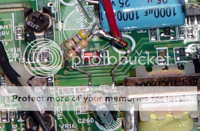
I got a idea for you, Try installing a resistor in series with the diode on the board. Try a 500ohm or something close, It might be enough resistance to drop you negative peaks. It has to be lower than 560 ohms or the current will go through R292 instead of your diode.
 
I'll try a resistor/diode in series this evening ........ or here shortly is this rain keeps moving in.
 
Joe's waveform looks much better however we have to remember it's a steady sine wave that is relatively easy to set the correct levels with in comparison to average speech. That is the key to this mod. Having to carefully set the gain so that the negative peak is not driven very hard into clipping. This greatly reduces the amount of compression the circuit can provide before the negative peak is driven into hard clipping that will require a filter to clean up.

Having recently worked with a few compressors and negative peak limiters, I can tell you that most peoples voices are not symmetrical. Simply connecting a microphone directly to a scope can verify how asymmetrical your own voice may be. You have a 50% chance that your modulation phase could benefit from this lack of symmetry in your voice. Using a small isolation transformer to switch phase, reversing the wires on many mic elements, or adding an active phase inverter can help determine if you voice is asymmetrical and if it's phased correctly so that it benefits the positive peaks.

If your voice is asymmetrical (very typical) and you use any effective NPC, you will see major improvements with proper phasing of the modulated audio. In some cases just getting this phase correct can give the effects of NPC without any components added.
 
Joe's waveform looks much better however we have to remember it's a steady sine wave that is relatively easy to set the correct levels with in comparison to average speech. That is the key to this mod. Having to carefully set the gain so that the negative peak is not driven very hard into clipping. This greatly reduces the amount of compression the circuit can provide before the negative peak is driven into hard clipping that will require a filter to clean up.

Yes if you set it up for a prefect %98 negative modulation with a 1k tone, the amount of compression does change between different audio frequencies, even at 400hz there is a noticeable change in negative peak compression. I have found that the lower frequencies go to zero volts a lot easier than higher ones. I also have found keeping the factory mod limiter intact helps keep the negative compression more equal across the frequency range of the radio.

The NPC mod is not perfect but in this case with 359's radio it can be improved on. I think for your average radio operator this mod give you the power, swing, and cleanest audio for the little work involved to do it right.
 
Having recently worked with a few compressors and negative peak limiters, I can tell you that most peoples voices are not symmetrical. Simply connecting a microphone directly to a scope can verify how asymmetrical your own voice may be. You have a 50% chance that your modulation phase could benefit from this lack of symmetry in your voice. Using a small isolation transformer to switch phase, reversing the wires on many mic elements, or adding an active phase inverter can help determine if you voice is asymmetrical and if it's phased correctly so that it benefits the positive peaks.

I might have to try that!
 
I'll try a resistor/diode in series this evening ........ or here shortly is this rain keeps moving in.

Keep us posted! It just might be an easier way to do this mod on a surface mount radio with out removing any components (y)
 
Well, here are the before and after pics, 50w peaking 225. I started with a 470ohm and it got better, but then I added another 470ohm in parallel and it got better yet. I thought about adding another to bring it down further, or just starting over with a 220ohm, but I really need to stop soldering around until I get that lighted magnifier, lol.

I have a feeling it'll all change tomorrow, but I think it can be done pretty easily. The diode he used is a glass diode, and I ordered 1n4001 diodes. I also think taking R292 out will make a difference too, it has to pull some current, right?

before ...........

a739108e.jpg


after ...........

7875c026.jpg
 
  • Like
Reactions: Pez
Keep us posted! It just might be an easier way to do this mod on a surface mount radio with out removing any components (y)
I bought some surface mount stuff, may as well get used to it I guess. I think what I'll do is tune it with the trimmer and then just put the same resistor/diode combo AT R292 instead of jumping R292 to C258. It should look cleaner, and there is no sense soldering around on that dinky little capacitor, lol. I'll just clean everything up with some solder wick before I finalize it.
 
Looks to me that you have already succeeded . . .
I thought about just buttoning it up, but it needs cleaned up a bit once I can see what I'm doing, I got a little messy around that cap. Plus I'd like to mess around with that trimmer a bit and see just how good I can get it. If I'm going to crash course on radios, I may as well experiment a little since my tech of 6 years won't respond to me any longer :unsure:

d8f28783.jpg
 
I've got a RCI 2995DX in the box too.

What you have done is created a v.cool thread here. I may well do this mod to mine as well now that I have seen what you have done here with yours - 359.

I would just shorten the leads on the resisitor side - if anything. With the waveform you've got as a record for the mod as demonstrated, I am recommending this thread now.
 
Last edited:
Looks good 359 (y) I think I might send all my surface mount stuff to you:tongue:

If your going to install the trimmer I would remove R292.
 
I've got a RCI 2995DX in the box too.
Now remember, this is the 2970n2, I don't expect it to be any different really when I do the 2995dx, but just the same, maybe stay tuned until I get them both done, lol.
 
Looks good 359 (y) I think I might send all my surface mount stuff to you:tongue:
If you think that's something, wait til I get my magnifier and I can actually see it :blink:


If your going to install the trimmer I would remove R292.
Yeah, if I leave the trimmer in or replace it with a fixed resistor, I think your right, I'll remove R292, clean up a little with some braid and stick the resistor/diode combo in the R292 hole.
 

dxChat
Help Users
  • No one is chatting at the moment.