bob bias using the lm723
Hey, where did you get that clamp stand from, I like it.

bob bias using the lm723
bob bias using the lm723
You can test it with using expensive pills.")
Do you have a source for those cheap pills that are used for testing.... LOL
Or how about the ones that don't heat up or blow if the amp takes off into self oscillation?
I could use 4 of them right now.
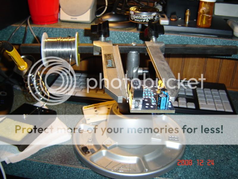
i have etched boards with ferric chloride in the past but not the bias boards, i drew the basic layout using the component sizes i was using and had some prototype boards etched and drilled,
if i were to do it again i would makes some changes, probably go partly surface mount and not bother with class c to make the boards smaller and neater.
bush, the boards are double sided tinned copper on fiberglass, they are thicker than i had anticipated,
i never bought a bias circuit but i remember somebody posting a pic of the psftech board, they were basic, i have not played with a circuit like that since the late 80's,
the active circuit works MUCH better than any passive system i ever saw,
as peakaboo said it would be wise to test your circuit before you stick it in an amplifier, i would clamp the output with a large diode to ground so you dont accidentally smoke the base emitter junctions.
yes, well seasoned. baw haw hawi bet you really enjoy your food then :sneaky2:
.7v will turn some transistors on too hard bush,
i would make a test rig up using a cheap audio transistor with similar dc current gain to the 2879's.
when you get to testing in the amp ( using basic tools ) start at under .6v, dont worry about current draw from the bias supply, it needs to NOT current limit at regular drive levels to keep it in class ab, you can look at the bias voltage, if it dont sag under higher drive levels you have enough current limit, you can always set your current limit to start folding back above a certain drive level when you are done,
( if you have poor rf isolation rf can mess with the regulation )
put the meter between the power choke and the power strip on the back of the output transformer so you can measure the idle current of the transistors,
put a dummyload on the amp for safe measure,
turn your bias supply down to its lowest setting,
activate the bias supply and look at the current drawn on the collectors, increase bias voltage while watching idle current, a pair of 2879's should draw about 2-300ma at idle in class ab ( other values can be used and still sound acceptable to the ears ), its handy to be able to measure both sides of the amp at the same time but not critical,
when you have each side of the amp set to the same idle current with no drive you can hook the radio up and watch the bias voltage as you increase drive level,
if the voltage stays stable you are in the ballpark, start warming the amp up and periodically chech your no signal idle current on both sections of the amp to observe how far they have drifted,
a well tracked bias circuit will show little change or a small decrease in idle current,
if you see an increase with temperature you are undertracking, if the idle current has significantly dropped you are over tracking,
keep your eyes open for sudden increases in current draw or silly watt readings some amps with low feedback can be provoked into self oscillation which can easilly end in smoke, i like to test using a current limited power supply whenever i can,
( touch wood i never made any smoke so far )
hope this helps.