
You are using an out of date browser. It may not display this or other websites correctly.
You should upgrade or use an alternative browser.
You should upgrade or use an alternative browser.
-
You can now help support WorldwideDX when you shop on Amazon at no additional cost to you! Simply follow this Shop on Amazon link first and a portion of any purchase is sent to WorldwideDX to help with site costs.
-
Retevis is giving away a new RA89R for Father's Day! Click Here for more info!
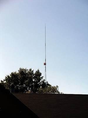
End Fed 1/2 wave antenna
- Thread starter HomerBB
- Start date
Homer, I seem to recall a 1/2 wave wants .05 wave length counterpoise, or about 22" on 27.2mhz. Maybe that would help flatten the SWR lower in frequency unless you want your tuning at 27.557
Not that it matters, but I took it down to put the Astroplane up and check it out as someone is interested in the AP. The AP is knocking the socks off that 1/2 wave and the .64 right now.
It always has.
(It's at 45' to bottom ring. One of the benefits of an AP is the ability to get it higher because it is lighter.)
It always has.
(It's at 45' to bottom ring. One of the benefits of an AP is the ability to get it higher because it is lighter.)
Not that it matters, but I took it down to put the Astroplane up and check it out as someone is interested in the AP. The AP is knocking the socks off that 1/2 wave and the .64 right now.
It always has.
(It's at 45' to bottom ring. One of the benefits of an AP is the ability to get it higher because it is lighter.)
Homer don't forget though, I see I've made the same request that NB made. I recall he talked about the same article I linked to your earlier over at QS.
You're in a perfect position to check this out with access to the matching network to add as much ground wire as you wish and to test the results with your analyzer. I never saw a difference using an inline meter.
Such a test may give us a clue to how much the A99, and similar end fed half waves need of the coax/mast to complete the antenna...like many discuss. If the required length is a very short piece of wire, like Yates says it is, then you will hear me preaching the idea more often and with a little more confidence.
I've always sorta questioned this, because I didn't see there was enough current in the area around the end of a 1/2 wave radiator to provide current for the radials, and expect them to do any work.
After reading Yates testing ideas, I though the matching device must be balancing the load somehow just like he said, and therefore might be mitigating the need for radials. I know there's lots of bare wire below the capacitor in the A99 matching device that might possibly be providing all the return currents necessary for it to work without radials. Same probably applies to the Imax.
On the other had, I believe the idea of using the feed line to provide return current in some antenna is valid, so my thinking is still mixed on this subject.
The main reason I question this is, first we hear many reports that adding the GPK to the A99 shows to make no difference. Second, the only difference I see is a very little narrowing of the bandwidth with the curve showing more of a bowl shape than with no radials. Otherwise this one goes back the first idea.
I have also put my VA1 analyzer meter on the feed point of my A99, and I didn't see anything strange going on, but I didn't isolate the mast so that test was not valid with my suspicious thinking. I have my A99, setup and mounted on an 2.5' foot insulator, right now to do that test. I have a 20' push up pole to test with, but I just don't have the energy or the will.
This is the only reason I asked you to do the test on your new 1/2 wave antenna.
I can do that, and likely I will.
I just needed to be sure the AP was in proper working order before it went to a new home.
I'm not making any money off of it, but a local is in need of it, and I want to build a new one of metal tubing.
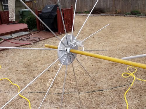
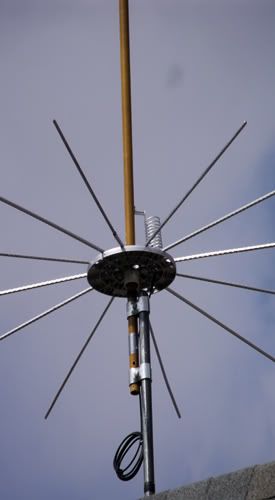
As for the GP testing on the 1/2 wave, not only can I attach a wire to it, but if you recall this set of radials below, I still have them and have gotten curious about what they might reveal. I also have the antenna isolated from the mast in the same manner as you see in the second photo below, and have from the beginning.
I just needed to be sure the AP was in proper working order before it went to a new home.
I'm not making any money off of it, but a local is in need of it, and I want to build a new one of metal tubing.
As for the GP testing on the 1/2 wave, not only can I attach a wire to it, but if you recall this set of radials below, I still have them and have gotten curious about what they might reveal. I also have the antenna isolated from the mast in the same manner as you see in the second photo below, and have from the beginning.
I can do that, and likely I will.
I just needed to be sure the AP was in proper working order before it went to a new home.
I'm not making any money off of it, but a local is in need of it, and I want to build a new one of metal tubing.
As for the GP testing on the 1/2 wave, not only can I attach a wire to it, but if you recall this set of radials below, I still have them and have gotten curious about what they might reveal. I also have the antenna isolated from the mast in the same manner as you see in the second photo below, and have from the beginning.
Homer, that is the way I isolated my A99 when I checked it with my VA1 at the feed point. I used some PVC inside the gate hardware, but Bob suggested that the antenna may still react because the parts are side by side and not above each other. Even so, I think I saw nothing on my analyzer that suggested the match was any different than using a feed line isolated or not.
My setup now allows the insulator to sit in the top of the mast, and that is the way I won't to test it next...just in case Bob is right.
I know it's a little difficult to tell, but in both cases the actual antennas are above the metal masts.
I like to do it that way whenever possible. I do not have too much evidence that it is better that way except my awareness of how much a dipole reacts especially to conductive things around it. I just like to keep the antennas away from things.
We'll see what's up in the next few days.
In the meantime, i am enjoying actually hearing something, and being heard when I call. I most certainly will be building a new AP as soon as I can.
interesting reading on the subject of feeding/matching an end fed 1/2 wave. some mention of radials vs high voltage at the ends of a 1/2 wave
http://www.eham.net/articles/9677
http://www.eham.net/articles/9677
I know it's a little difficult to tell, but in both cases the actual antennas are above the metal masts.
I like to do it that way whenever possible. I do not have too much evidence that it is better that way except my awareness of how much a dipole reacts especially to conductive things around it. I just like to keep the antennas away from things.
We'll see what's up in the next few days.
In the meantime, i am enjoying actually hearing something, and being heard when I call. I most certainly will be building a new AP as soon as I can.
Homer my post below was in error. I should have used the word "mount" where I said "isolated." I use the same type of gate brackets to secure some of my antennas though and when I isolate the mast from the radiator I placed some PVC material under one side of these brackets, and then check to make sure there is no continuity between the two elements.....
Homer, that is the way I isolated my A99 when I checked it with my VA1 at the feed point. I used some PVC inside the gate hardware, but Bob suggested that the antenna may still react because the parts are side by side and not above each other. Even so, I think I saw nothing on my analyzer that suggested the match was any different than using a feed line isolated or not.
My setup now allows the insulator to sit in the top of the mast, and that is the way I want to test it next...just in case Bob is right.
I kind of hate to even pose my curiosity to you Homer. So, don't get upset with me, but I'm confused a little with exactly how these antenna radiators are physically isolated from the masts. I think I see how the radial hub and the radials are insulated from the radiator, and correctly so, but I don't see how the whole antenna is isolated from the mast.
In each case of the two antennas they are mounted to fiberglass tubes around five feet long. All of the electrical parts are either within or along side the upper 2.5 - 4 feet of the fiberglass. One of them is a yellow FB tube, the other is a dark green FB tube. The gate clamps are attached only to the lower part of the FB tube on the yellow one. The green tube is set into the top of the metal mast. Never is the metal mast anywhere near the electrical parts of the antennas.
In each case of the two antennas they are mounted to fiberglass tubes around five feet long. All of the electrical parts are either within or along side the upper 2.5 - 4 feet of the fiberglass. One of them is a yellow FB tube, the other is a dark green FB tube. The gate clamps are attached only to the lower part of the FB tube on the yellow one. The green tube is set into the top of the metal mast. Never is the metal mast anywhere near the electrical parts of the antennas.
Coax choked alongside the fiberglass, well above the top of the mast?
I don't see why you couldn't use 22" of coax shield under the 1/2 wave, and down to a CMC choke at that point as a .05wl counterpoise.
In each case of the two antennas they are mounted to fiberglass tubes around five feet long. All of the electrical parts are either within or along side the upper 2.5 - 4 feet of the fiberglass. One of them is a yellow FB tube, the other is a dark green FB tube. The gate clamps are attached only to the lower part of the FB tube on the yellow one. The green tube is set into the top of the metal mast. Never is the metal mast anywhere near the electrical parts of the antennas.
I still don't get it, but it may be a secret.

You guys must think I'm crazy, some have said as much, but in my personal experience testing radials on several 1/2 wave antennas I found radials made no difference that I could tell, in performance, on the inline meter, or when using my analyzer. Here is my Wolf 1/2 wave antenna without radials, where I added radials 12" below the insulator and the tuning ring.

Now I do models of the 1/2 wave, end fed with no radials and a center fed as a comparison, and little to no difference in gain or angle. I also included a 1/2 wave end fed with radials and again all about the same performance according to these models. It is also important to note when looking at the pictures you might see that the patterns for these antennas are all about the same where the rubber meets the road.
So, I have <gotproof> some evidence that tends to prove what I claim. How about someone else out there help us figure it out instead of just words, looking at some pictures, and listening to what we all hear on the air. Maybe something to consider.
View attachment Homer's .50 wave ideas.pdf
Last edited:
Certainly no difference on the lowest lobe, only on the upper lobes mostly in the nulls.
I have some data from the analyzer with a single radial and without any. I'll post it when I can.
I have some data from the analyzer with a single radial and without any. I'll post it when I can.
Certainly no difference on the lowest lobe, only on the upper lobes mostly in the nulls.
I have some data from the analyzer with a single radial and without any. I'll post it when I can.
That will be interesting Homer. I have a feeling my venting may have been all in vain and my idea is about to be shot down for good.
Aren't we lucky that the difference in those models was high up and in the nulls...where few people talk in the CB band.
dxChat
- No one is chatting at the moment.
-
-
-
dxBot:boog351 has left the room.
-
@ BJ radionut:
June VHF
The American Radio Relay League (ARRL) is the national association for amateur radio, connecting hams around the U.S. with news, information and resources.www.arrl.org