A few things...
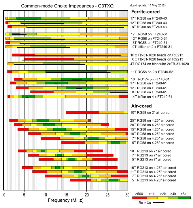
Five wraps on an eight inch form for LMR-400 is to many wraps. LMR-400 is very close to the diameter of RG-213, and the RG-213 data from the chart posted above will get you very close. Five turns on an eight inch diameter form will push the use able frequency below the CB band. Look at the 5 turns of RG-213 on a 7 inch form as a starting point, and the larger 8 inch form will lower the effective choking frequencies even further.
When it comes to choke placement, there is one correct location, and that is as close to the feedpoint as you can get it. The further away from the feedpoint the choke is the more common mode currents will flow on the stretch of coax between the feedpoint and the choke. While a foot or two isn't enough to drastically alter anything, if you put the choke far enough away, and common mode currents are present, they can actually affect the tuning of the antenna. That being said, just because you have an antenna up doesn't automagically mean you have to deal with common mode currents. Some antenna designs are naturally better at dealing with them than others.
Research is always a good thing. I always encourage this line of thinking. Just make sure your sources are reputable. There are several good books on the topic available, I highly suggest starting with those, even if they are more expensive than looking things up on the internet...
Be careful about things that are supposedly set in stone when it comes to antenna theory, some things are, but many things that people believe are set in stone really are not. Someone who truly understands antenna theory will easily be able to point these out.
Also, be careful about who you believe. There are those that appear knowledgeable at first glance, but really know far less than they think.
And finally experience, in and of itself, will only get you so far. It is often touted as the end all and be all of antenna knowledge, but without an understanding of theory to frame that experience, it will only get you so far. Look for someone who has both. Such people are much harder to find, but they do exist.
The DB