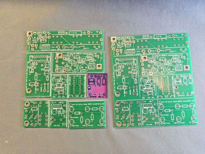
So here's the next piece of this puzzle to get addressed. Different slice highlighed in purple this time.

Got all 50 of this one built. Now still need to add wires for the carrier control.

This one goes into AM-only CB radios like a Cobra 29. The wire jumper that feeds power to the driver transistor gets pulled out. The two bare wires on this module go into the two holes where the jumper was removed. It comes with a piece of industrial-grade adhesive foam on the transistor. This stuff is called "VHB" and sticks like elephant snot to a clean surface.

It's best to swab the surface of the heat sink where it will be attached with your favorite non-residue solvent. Rubbing alcohol works fine in a pinch.

Any tech who doesn't want to be a Kevorkian will inspect both sides of the mica washer under the final transistor before making any high-performance mods, or even turning up the modulation limiter. This one was nearly dry on the heat-sink side.
Typical.

The two bare wires on the PNSVK module go into the jumper-wire holes. They're marked "JP36" in this version of the radio.

A good squeeze is necessary to bond the VHB's adhesive to the heat-sink surface.

I used the radio's front-panel "SWR Cal" control to attach the three contr
ol wires. It's a tight squeeze to get them soldered, but doable.

What remains on the top side is to strip a half inch from the end of the green ground wire and insert it into the handy hole at the rear corner of the pc board.

The reason for stripping so much from the end of the green wire is that you'll have to lap-solder it to nearby component leads near that hole.

All that remains now is to set the minimum carrier power you want with the SWR Cal knob all the way to the left. That's what the trimmer pot on the PNSVK is for.
I hate to disable a radio function even when I hijack a control on the front. The SWR meter can still be used by installing a 5.1k or 4.7k resistor here, with the clockwise and wiper wires at one end, the ground wire at its other end.

Slide a sleeve over the mess to keep it from getting into trouble.

Of course, all these loose wires need to get zip-tied down securely. Shouldn't need a pic for that detail.
This one's not ready for Ebay yet, but that's the idea.
And yeah, it works in pretty much any 40-channel AM-only CB. Not recommended for a 23-channel radio. Makes a lot of them get squirrelly.
73
Got all 50 of this one built. Now still need to add wires for the carrier control.
This one goes into AM-only CB radios like a Cobra 29. The wire jumper that feeds power to the driver transistor gets pulled out. The two bare wires on this module go into the two holes where the jumper was removed. It comes with a piece of industrial-grade adhesive foam on the transistor. This stuff is called "VHB" and sticks like elephant snot to a clean surface.
It's best to swab the surface of the heat sink where it will be attached with your favorite non-residue solvent. Rubbing alcohol works fine in a pinch.
Any tech who doesn't want to be a Kevorkian will inspect both sides of the mica washer under the final transistor before making any high-performance mods, or even turning up the modulation limiter. This one was nearly dry on the heat-sink side.
Typical.
The two bare wires on the PNSVK module go into the jumper-wire holes. They're marked "JP36" in this version of the radio.
A good squeeze is necessary to bond the VHB's adhesive to the heat-sink surface.
I used the radio's front-panel "SWR Cal" control to attach the three contr
ol wires. It's a tight squeeze to get them soldered, but doable.
What remains on the top side is to strip a half inch from the end of the green ground wire and insert it into the handy hole at the rear corner of the pc board.
The reason for stripping so much from the end of the green wire is that you'll have to lap-solder it to nearby component leads near that hole.
All that remains now is to set the minimum carrier power you want with the SWR Cal knob all the way to the left. That's what the trimmer pot on the PNSVK is for.
I hate to disable a radio function even when I hijack a control on the front. The SWR meter can still be used by installing a 5.1k or 4.7k resistor here, with the clockwise and wiper wires at one end, the ground wire at its other end.
Slide a sleeve over the mess to keep it from getting into trouble.
Of course, all these loose wires need to get zip-tied down securely. Shouldn't need a pic for that detail.
This one's not ready for Ebay yet, but that's the idea.
And yeah, it works in pretty much any 40-channel AM-only CB. Not recommended for a 23-channel radio. Makes a lot of them get squirrelly.
73