Techno1,
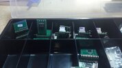
There are really only two kits like this in existence right now, and one of those is the digimax kit.
It may be a bit expensive but you'll find it's worth it because these kits have been around for a a long time and come with pretty good install instructions.
that said, doing channel mods to a radio is never a 'plug and play' situation as there are always things to re-tune, and there are always chances to ruin the radio while installing the new kit.
many a radio has been put on a shelf permanently because the ad said the kit was easy to install.
ive installed quite a few of these kits and i wouldn't recommend anyone try it who doesn't already work on electronics because once you are done and it doesn't work you are going to be completely lost on how to get it working and will be on your own because no shop is going to want to try to fix your work.
better to just have a shop do the install/modifications for you in the first place.
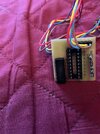
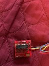
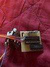
the kit in your picture comes from here i think:
cb-radio repair, avr firmware programming, Elektronic, repeater, modification, frequeny extension, transmitter, rogerbeep, echo module, FM, FM-module, PLL-module, DDS module, ssb-module, ts340
funkservice.at
this is from Germany i think and i've never installed one of his kits.
hope this helps!
LC

")