• You can now help support WorldwideDX when you shop on Amazon at no additional cost to you! Simply follow this Shop on Amazon link first and a portion of any purchase is sent to WorldwideDX to help with site costs.

My Guess is It's An Antenna Specialists

HomerBB

Sr. Member
Jan 4, 2009
3,933
2,633
273
68
Rogers, Ar
My Son-in-law gave me an antenna he found in his attic. His first impulse was to throw it away, and decided to throw it my way.

Between a friend and I, we think it may be an Antenna Specialists
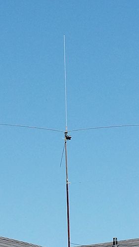
It is a 1/4wave GP.
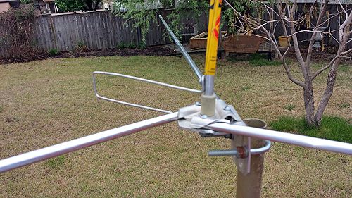
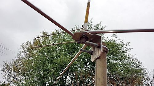
There are three radials, all of which are the exact same length as the vertical radiator, and are not drooping, but straight out horizontally around the vertical. It has a hairpin matcher to handle impedance.

638_zpsdb60acf1.jpg


653_zpsd7754242.jpg


4142_zps8b7de376.jpg


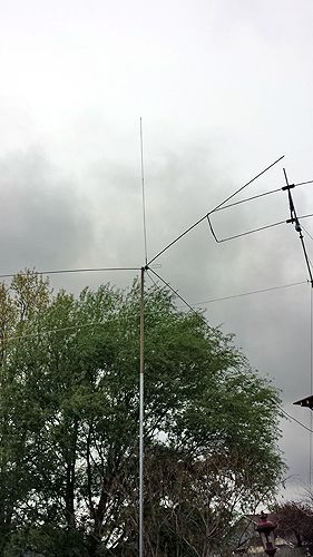
Only 15' up to antenna bottom.
 

If you took the hair pin off an the top section was along side the top element it looks like my antenna specialist scanner antenna so I think your right about the manufacture .
 
  • Like
Reactions: 1 person
Homer I can't be sure, because I can't see specifically how this antenna is fed except the center pin in the PL connector looks to me to connect directly to the radiator somehow...maybe using a short wire up-inside the isolator.

The offset wire setup does look like a hairpin, but to me it only appears to be a form of static arrestor making a direct path to ground for the radiator, and does not perform as a tuner like a hairpin.

I modeled it as best I could using 4 x 107" elements and making a guess that the small wire setup on the side was 8" x 2" inches, but this did not fix the mismatch. In fact the mismatch got worse on adding the wire element. Plus the antenna, with or without this added wire, shows a very bad high angle pattern either way.

In my opinion this antenna was more than likely used as a "receiving antenna only" maybe for a scanner...sorta' like 357 suggested.

How does it show on TX using your SWR meter? Or your 259b? My model with the wire added shows over 3.00:1 SWR and 2.10:1 without the added wire.
 
Last edited:
Homer I can't be sure, because I can't see specifically how this antenna is fed except the center pin in the PL connector looks to me to connect directly to the radiator somehow...maybe using a short wire up-inside the isolator.
Marconi, the vertical is directly fed to the PL, but not with a wire. I believe it is threaded inside the bottom of the vertical radiator tube and screws directly onto the upper stud of the coax connector. I believe this is similar to the Starduster.
The offset wire setup does look like a hairpin, but to me it only appears to be a form of static arrestor making a direct path to ground for the radiator, and does not perform as a tuner like a hairpin.
Perhaps the loop is not a matcher. It connects at one end to the radiator, and at the other end to the radials hub. I know the impedance is higher on a 1/4 wave GP if the radials are horizontal. I figured this resolved that issue.
I modeled it as best I could using 4 x 107" elements and making a guess that the small wire setup on the side was 8" x 2" inches, but this did not fix the mismatch. In fact the mismatch got worse on adding the wire element. Plus the antenna, with or without this added wire, shows a very bad high angle pattern either way.
Your dimensions guesses are good.
I can not speak to the pattern and have to trust your model. Conditions are worthless here for anything, both local and DX is very quiet so I can not even speak to whther it has ears, etc.
In my opinion this antenna was more than likely used as a "receiving antenna only" maybe for a scanner...sorta' like 357 suggested.
Maybe so.
How does it show on TX using your SWR meter? Or your 259b? My model with the wire added shows over 3.00:1 SWR and 2.10:1 without the added wire.
The 259B needs to go back for calibration. The SWR read very good across CB and above with it, and X=0 for resonance followed that range. Impedance was in the 30s range.
The SWR meter with a grant XL hooked up shows 1.0:1 on ch 1 and ch 20 with 1.1:1 on ch 40.


I hope you're well.
 
that is either a newtronics 1/4 wave 11/10 meter antenna if i remember or an radio shack 1/4 ground plane,,,,,,21-901 in 1975 radio shack catalog 12.95 new...... marconi is right about the hairpin is a static arrestor,,, that is how radio shack advertised it....
 
Last edited:
  • Like
Reactions: 1 person
that is either a newtronics 1/4 wave 11/10 meter antenna if i remember or an radio shack 1/4 ground plane,,,,,,21-901 in 1975 radio shack catalog 12.95 new......

Thanks of the infor MS, I think you might be right. According to this link, Radio Shack "Archer #21-901 Ground Plane", it looks to be a RS 1/4 wave with what RS calls a "Mostest Static Arrestor." The "Mostest idea" does not look to shown up in the artist rendering however, but they talk about it in the ad.

This antenna has the look of Hy-Gain, and I think they built a lot of antennas for Radio Shack.

Also take note of the FCC comment at the bottom of the RS ad piece. As history goes, and if you ever wondered when this all happened in time, such a comment may be telling of the year, 1975, when the FCC height changed.

This is probably the antenna that Homer is reporting...and the hairpin looking wire no doubt has some improving effects on the 1/4 wave match with horizontal radials. You won't likely see as good of match with a 1/4 wave and horizontal radials without some matching device added...or unless you slant the radials down at least 45* degrees.

So, it must be a hairpin like he says.
 
Last edited:
The RS 1/4 wave antenna for $ 12.95 was my first antenna being on a budget an still in High School an it didn't have the arrestor on it not saying it wasn't added on an up-dated version . I did enjoy seeing the original add I always thought I paid $ 20 for it .
 
  • Like
Reactions: 1 person
Thanks for the leads on what it is. The RS model does look close, but not enough details to see the wire loop as you said.

Marconi, the vertical and the three radials are all 104" long. 2 sections, first is 1/2" x 59", the other 3/8" x 44".
The hairpin wire is 7.5" x 1.5" spacing apart from each leg of it.

I now have it at 27' high to the coax connector.

It is choked just beneath the connector. The SWR is 1.0:1 across the CB band.

4305_zpsece3e17e.jpg
 
Thanks for the leads on what it is. The RS model does look close, but not enough details to see the wire loop as you said.

Marconi, the vertical and the three radials are all 104" long. 2 sections, first is 1/2" x 59", the other 3/8" x 44".
The hairpin wire is 7.5" x 1.5" spacing apart from each leg of it.

I now have it at 27' high to the coax connector.

It is choked just beneath the connector. The SWR is 1.0:1 across the CB band.

I'll try and see if your dimensions help the match for my Eznec model.

Did the 104" elements look to have enough material to stretch out to 108" like the ad suggested for the length of the elements? If not, then we still don't have the answer...who made the antenna.
 
I did some looking around MFJ uses a hair pin clip like that on their 6m 1/4 wave ground plane if I recall mfj 1756 . It might not be it but it looks similar in the pic . Just my 2 cents .

Sent from my NB09 using Tapatalk
 
The MFJ-1756 has four radials. Mine has three. The hairpin on theirs is much bigger proportionate to the rest of the antenna. For course, this one I love have is longer, too.

You are certainly trying to figure it out. Thanks.

Marconi, did you model it again? It is working well enough seems. The Moxon outworks it, but for a 1/4 wave it does quite well so far. Worked a little DX with it, now I
ot much. A little local, even less.

No Homer, making the hairpin smaller only made the match get a little worse, and the gain dropped noticeably below 2 dbi for some unknow reason. The adjustment I made was only a 1/2" change in hairpin dimensions.

I have not fiddled with this model much, I wanted to make this one fast and simple. I may find I made some stupid mistake. For example: I did not make a radial hub to attach the radials offset to the isolated radiator. That might make some difference. I have noticed this happen in my Starduster model, but I don't remember the effects or results. I may look back at that model if I can find it.

I'm scheduled to be at the hospital again tomorrow for more testing. Give me some time and I'll get back to the model.
 

dxChat
Help Users
  • No one is chatting at the moment.
  • @ Wildcat27:
    Hello I have a old school 2950 receives great on all modes and transmits great on AM but no transmit on SSB. Does anyone have any idea?
  • @ ButtFuzz:
    Good evening from Sunny Salem! What’s shaking?
  • dxBot:
    63Sprint has left the room.
  • dxBot:
    kennyjames 0151 has left the room.