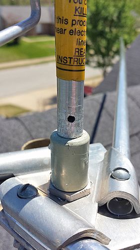
imho it looks like a dollar match idea to raise the feed-point impedance at resonance to 50ohm by shortening the radiator to add capacitive reactance and shunting the feedpoint with a corresponding inductance, dc ground is a bonus.
That's also a possibility Bob but going by the stated 107" I assumed the capacitor was in the base, centre pin feeding an internal smaller tube separated from radiator by a surrounding dielectric, similar to an internal gamma match.
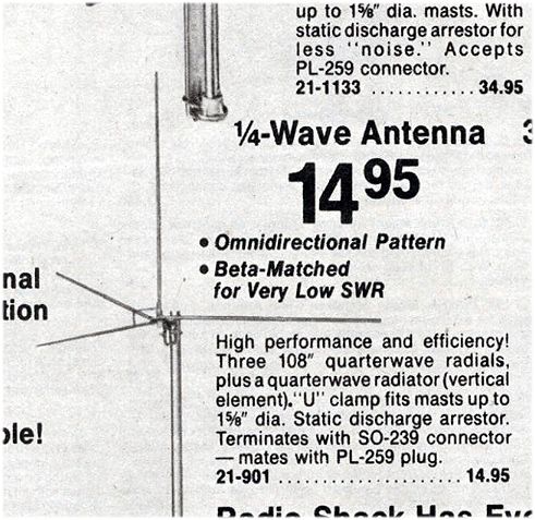
but it could be either without closer inspection. why anyone would go to the hassle just to get a perfect 1.0:1 vswr is beyond me, its no biggie a vswr of around 1.4:1 and they are generally damn fine antennas and highly underrated like the starduster m400
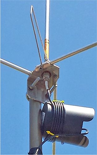
the antenna warning label looks very similar to my old antenna specialists mighty magnum 3, so could be A/S, but could just be a standard sticker many companies use.
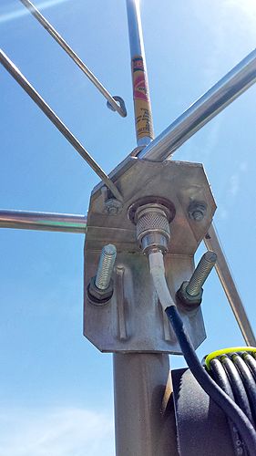
its deffo an inductor/hairpin grounded at one end so there will be capacitance either where i suggested or where Bob has suggested, as long as swr is good, ie below 2.5:1 it will work and work well, have no doubt about that Homer, i wouldn't worry about the goof mate, at least now you know how to work out expected vswr from feed impedance. you always divide the larger number by the smaller one to get the ratio
")
17 ohms is roughly the same vswr as 150 ohms, both show 3.0:1 vswr. in the case it looks like the far bigger gap between 50 and 150 is greater than the difference between 17 and 50, but the ratio is actually the same.
On a separate note for those interested or with radios/swr meters you may think are misreading:
A handy wee tip if you want to calibrate an analyser or swr meter is get a T junction and two identical parallel resistive dummy loads, swr should be 2.0:1 as paralleling them will give half of one of their individual resistances, or 25 ohms, may be 27.5 if both are 55 ohm, which is common on a cheap dummy load.
you can measure true resistive value of dummy load with a multimeter on centre and outer pin set to a low ohms range, 100 or 1000 range is ideal, might be 200 and 2000 on some meters as long as its over 50 your sorted.
if you can find a 3 way splitter 3 x 50 ohm dummy loads will give a 3.0:1 vswr and 0 reactance and should show around 17 ohms resistance, will be 16. something as the values on either side are purely resistive.
Cheap and cheerful trick that works for external swr meters, built in ones or even analysers if you know the presets that calibrate it.
Also allows checking its accuracy if you doubt it, will certainly confirm if your swr meter or antenna/coax is fucked.
the exact same thing is done with a cophase harness, except instead of two 50 ohm dummy loads, the antenna swr is inverted to 100 ohms by q section on either side then paralleled to give the required 50 ohms which is half of one 100 ohm side. if they were added in series they'd show 200 ohms as they would combine impedances.
2 identical resistors give half the value of one of their values,3 1/3 value, 4 1/4 value, 10 1/10th value and so on, but only works for equal resistors, there's a slightly different formula for unequal resistances. If you want to learn that, google resistances in parallel.
its how many dummy loads are made, 20 x 1000 ohm resistors in parallel give 50 ohms, 1/20th of an individual one, but they will handle 20w if 1w resistors, 40w if 2w resistors and so on,wattage handling is the number of resistors times their power handling/dissipation, you can build a dummy load to handle just about any power level or impedance/resistance this way, often oil is added to cool them or they are air blown to allow slightly higher power briefly, 1% tolerance resistors are best for this job but could use higher percentages and just measure them to find ones that are either the exact same or very very close, all the exact same gives most accurate results