• You can now help support WorldwideDX when you shop on Amazon at no additional cost to you! Simply follow this Shop on Amazon link first and a portion of any purchase is sent to WorldwideDX to help with site costs.

Dimensions for 1/4 wave CB Ground Plane?

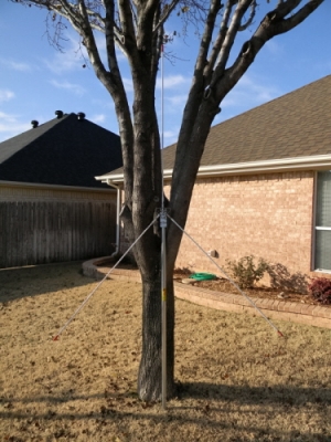
I think the picture of the hub is an original GPK hub with four radials slanted down and three radials horizontal. I just drilled and tapped for three added horizontal radials.

I don't recall working my Marconi on air with only one sloping radial, but I did test the idea near 18' feet. My Eznec model of the idea also shows one radial will work very well, and depending on your mounting being well into the clear and at least 18' feet high, the antenna should work just fine.

As I removed radials from my antenna during my testing, I did find the antenna, with only one slanted element (radial), the match tended to be more like a full 1/2 wave dipole R=70 ohms J= <>0 ohms. So the match suffered a bit, but it was nothing to worrying about, the SWR was still below 1.50:1 at the radio.

Can you briefly explain to me how an impedance of 70 ohms affects performance compared to the desired 50 ohms? I've never understood the effect of impedance on antennas.

Also, would the use of a 1:1 current balun fix the 70/50 mismatch? Or would this be unnecessary?

Thanks!
 
Last edited:
Can you briefly explain to me how an impedance of 70 ohms affects performance compared to the desired 50 ohms? I've never understood the effect of impedance on antennas.

Thanks!

If we tested your idea in the real world just using your radio and a good inline meter between the antenna and the radio...I don't think you would realize a difference at all.

Below is an Exnec model of a center fed vertical dipole showing an impedance of 72 ohms that is resistive at the fed point like you suggest. This is vs. a similar antenna with a 50 ohm match and resistive at the feed point due to slanting the bottom element up a bit again as suggested in this thread.

This shows a slight advantage for the straight vertical dipole with a less than perfect match, but IMO the difference even though the antenna with the better match shows a bit less gain and a 5* degree rise in maximum radiation angle.

I hope this help answer your question.

See model below.
 

Attachments

  • Verticle dipole vs. a V shaped in FS..pdf
    805.7 KB · Views: 14
Last edited:
If we tested your idea in the real world just using your radio and a good inline meter between the antenna and the radio...I don't think you would realize a difference at all.

Below is an Exnec model of a center fed vertical dipole showing an impedance of 72 ohms that is resistive at the fed point like you suggest. This is vs. a similar antenna with a 50 ohm match and resistive at the feed point due to slanting the bottom element up a bit again as suggested in this thread.

This shows a slight advantage for the straight vertical dipole with a less than perfect match, but IMO the difference even though the antenna with the better match shows a bit less gain and a 1* degree rise in maximum radiation angle.

I hope this help answer your question.

See model below.

That throws me for a loop. I am talking about a ground plane with a vertical element and a single radial slanted downward at 45 degrees. Not a vertical or V dipole.

Let me rephrase my question. Would the impedance at the feedpoint of the GP I described above be closer to 70 ohms or 50? And if 70, what can be done to lower it?

Sorry for the confusion. My fault.

Jim

I used the dipole because it has a match near 70 ohms as you described, and it is at resonance (resistive). It is also pretty close to similar to what you described...a GP with a single radiator and a single slanted down radial. Check the last page of each model for the source data (match).

I called it a V, because that is basically what it is a V shaped dipole radiating vertically. It also shows a match that is resistive and producing a match at or near 50 ohms at the feed point. Since this antenna has a single radials, so to speak, it wants to look like it does...not what you think it does. I also noticed this same thing years ago when I studied the 1/4 wave 102" whips and making a base station antenna out of whips.

The antenna with more radials is more symmetrical, so it will produce a 50 ohm match with the radials at a much lower angel. Maybe this is what you were expecting to see. I lowered the single radials in this case to 45 degrees at first, but the antenna wanted the radials to at a bit higher angle with the radial in order to produce a 50 ohm match...so I raised the bottom radial up some. The antenna also wanted to be a bit longer as well to be resonant near 27.205. Note: the bottom is actually not a radial. This is a dipole and the bottom element straight or slanted is an antenna radiating element, but it does admittedly look like a radial.

Try checking all of the results out again. As I understood your request...you asked for the difference in impedance only, and I figured that meant the difference in gain, between an antenna with 70 ohms and one with 50 ohms. I didn't understand you were looking for a particular look for the antenna with a single slanted down radial.

The answer to your question is the single slanted element will show you a match nearer 50 ohms, but being a single element and not several radials, will in part, determine the angle...so it might not look like you imagine. The angle of this element varies the impedance at the feed point and several things are at play.

Sorry. If you still have something else in mind, draw me a picture by hand and post it...I'll try again.


Ah-ha! Now I understand!
My yet-to-be-built 1/4 wave GP with a single 1/4 wave radial is basically a dipole and should perform satisfactorily, but I won't be able to set it up for maximum efficiency because I won't know at exactly what angle to slant my radial since I don't have an antenna analyzer. Guess I'll put it at about 40 degrees.

One more question if you don't mind.

If a GP of this nature is basically a dipole with its bottom leg bent, should the bottom radial (leg) be isolated from the metal mast just as the top element is? And if it is isolated, what makes the antenna a "ground plane"?

Thank you!

My antenna's with a 1/4 wave radiators do not have the radials isolated...they instead are connected directly to the ground at the feed point. I have read guru's saying the only way to get a 1/4 wave GP to produce a perfect setup...is to isolate the radials from the ground however.

I don't think I would ever be able to see the difference just operating my radio. Not to worry!

71, just about any angle will work, and IMO 40* degrees is fine. The impedance values shown for my models are values at the feed point. You will likely be seeing the match at the radio end of your feed line...there is almost always a difference in our CB setup.

Usually what guru's talk about with antenna discussions and articles is typically always...very technical. The differences they consider important are often very small.
 
Ah-ha! Now I understand!
My yet-to-be-built 1/4 wave GP with a single 1/4 wave radial is basically a dipole and should perform satisfactorily, but I won't be able to set it up for maximum efficiency because I won't know at exactly what angle to slant my radial since I don't have an antenna analyzer. Guess I'll put it at about 40 degrees.

Just so you know...

An antennas efficiency has nothing to do with the antenna's SWR. Things like ground losses are the causes of an antennas efficiency.

Further, just because some power is reflected because you don't have a perfect SWR match, due to a phenomena called re-reflection, most of that power (in most cases) make it back to the antenna to be radiated.

In any case, even if you mistakenly assumed all of the reflected power due to a non-perfect match was lost, other inefficiencies in an antenna will generally still have a much larger effect.

When it comes to actually measuring an antennas efficiency, SWR is not actually a part of that measurement.


The DB
 
  • Like
Reactions: Marconi
Thanks, guys.

Have been hanging around WorldwideDX off and on for several months now and I think the light bulb in my 61-year-old head finally lit. Spent most of that time duking it out with all the technical jargon and have the cuts and bruises to show for it. Now that it's starting to click I think I'll stay in the ring. I might even get my Technician and General tickets, move to the Ham forums, and debate the pros and cons of a flat G5RV Jr. at 15' versus an Alexloop looking through my bedroom window. LOL

Thanks again!
Jim
 
Last edited:
  • Like
Reactions: The DB
  • Like
Reactions: hotrod
I've often thought about making my own M400 as HomerBB did but with a 102" steel whip and 4' Firestiks as the radials rather than 103" wires. But then evil technical jargon would rise up and rear it's ugly head with promises of inefficiency, poor take-off angles, and the such which I never fully understood because my first homemade GP using a 4' Firestick as the vertical element and two 4' Firestiks as radials (slanted at 45 degrees) seemed to work pretty good. All I'd have to do is move the vertical down as a 3rd radial and replace it with the steel whip.

2758-1386450923-042538a758ed2f0e90ecdb0b2650679a.jpg
 
Be sure and check your shipping.
Here is the Sirio M400 antenna at about $80 dollars and $9.50 shipping. Amazon product ASIN B008NSS0Y4I don't know for sure about H & Y, but I have heard Coopers gets and arm and a leg for their shipping.

The thing I was trying to point out if you order all of these different pieces with shipping for the individual parts it would cost more than just buying one and get it all at the same time. The box these come in is about six feet long and you pay a premium for over sized package. Most tubing is sold in ten foot lengths and you can get a vendor that will cut them down for you. Some charge for this and some don't.
Plus all of it fits together and screws hardware is included.
 
  • Like
Reactions: chrisman686
Thanks, guys.

Have been hanging around WorldwideDX off and on for several months now and I think the light bulb in my 61-year-old head finally lit. Spent most of that time duking it out with all the technical jargon and have the cuts and bruises to show for it. Now that it's starting to click I think I'll stay in the ring. I might even get my Technician and General tickets, move to the Ham forums, and debate the pros and cons of a flat G5RV Jr. at 15' versus an Alexloop looking through my bedroom window. LOL

Thanks again!
Jim

This is a great place to learn about things like antennas. A lot of good information here, its just a matter of finding it or asking.

Good luck on your ham testing.


The DB
 
The thing I was trying to point out if you order all of these different pieces with shipping for the individual parts it would cost more than just buying one and get it all at the same time. The box these come in is about six feet long and you pay a premium for over sized package. Most tubing is sold in ten foot lengths and you can get a vendor that will cut them down for you. Some charge for this and some don't.
Plus all of it fits together and screws hardware is included.

Good point.

Thanks!
 
This is a great place to learn about things like antennas. A lot of good information here, its just a matter of finding it or asking.

Good luck on your ham testing.


The DB


Thanks, DB.

I think I'd be interested in a QRP rig and portable antenna if I make the switch. However, CB still fascinates me. The equipment and the culture. I never really got over the 1970s craze.
 

dxChat
Help Users
  • No one is chatting at the moment.