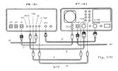
The FRG-7 and FL-101 mute in reverse. The FL-101 mutes when the contact is ungrounded and the FRG-7 mutes when the contact is grounded. The FL-101 uses Pin 10 for this. The FRG-7 is forced to share Pin 9 with the amp key. The problem with this scenario is that there is 9vdc present at the muting connection of the FRG-7 which will key the amp relay. Here are my findings.
So here is an update on where this project stands. I was unable to develop a successful method for muting the FRG-7 via the FT-101E directly while isolating the 9vdc at the muting connection of the FRG-7 that caused the amplifier relay to key. I was SUCCESSFUL however in muting the FRG-7 by using the microphone which isolates the 9vdc from the FT-101E thus eliminating the 9 vdc problem. I use an amplified Silver Eagle D104 in conjuction with the FT-101E. The FT-101E mic plug only utilizes 3 of the 4 microphone pins...position number 4 being empty. To achieve this it will require modification to the microphone as well as the addition of a wire to the FT-101E.
MIC MOD
The microphone tabs/fingers require modification in order to work. Using a non-modded mic on the FT-101E will not affect anything other than the FRG-7 would be muted upon plugging in the mic. If the FRG-7 were off operation would be normal.
To start, my D104 uses a 4 wire cord so the yellow wire is currently floating and the blue wire is connected to the shield finger (E).
The mic mod is quite simple. There is a separator/isolator that isolates the violent wire (C) finger from the brown wire (D) finger. The first step is to relocate this separator/isolator. It will be moved in between the violet wire (C) finger and audio wire finger (B) which comes from the mic cord. This leaves the violet wire (C) "floating" on my particular mic i.e. no contact made with the brown wire (D) finger. YMMV and the finger may need to be bent to create the necessary space to prevent the brown and violet wire tabs from making contact in the resting position. As can be seen in the attached image, when the ptt switch is depressed the violet wire (C) finger and the brown wire (D) finger will now make contact grounding the violet wire (C) finger. If you trace the violet wire to the amplifier board you will see that it is a dead connection (on my mic) that makes contact with no other components. This wire can be left in place, removed from the finger or removed entirely. In my case I left the wire soldered to the amp board but removed it from the finger to create more room for the next step.
The next step is to relocate the black mic cord wire (J) to the violet wire (C) finger. Now, when the ptt switch is pressed, the black mic wire will ground to the brown wire (D) finger.
RADIO
Now that the mic has been modded, a wire will need to be soldered to the empty position (position 4) of the mic plug on the radio. You will then run this new wire to the ACC (11 pin accessory socket) on the back of the radio. Position 11 of the ACC socket is empty and you will install the new wire at this location. The 500vdc caps are in this location so MAKE SURE that they have been properly discharged! Running a piece of foil, card stock etc around the ACC socket will help to prevent you from damaging nearby wires.
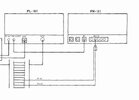
You will now need to install the ground and muting wires that will run to the FRG-7. In my case I used a section of RG8 coax that I had left over from another project. The ground wire will be soldered into position 8 (along with the ground wires for the amplifier relay cable and the ALC cable. The muting wire will get soldered into position 11. Once completed the ACC plug should be wired as such. Position 7 ALC, position 8 Grounds, position 9 amp key and position 11 muting line for the FRG-7.
Now all that is left is to connect the ground and muting cable to the back of the FRG-7. The mic will now mute the FRG-7 when the PTT switch is pressed.