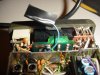
I have successfully done the MARS MOD to my Icom IC-2AT, heres some pics
"Mod #1:
Some of these radios were sold with only 144-148Mhz coverage (USA) or 144-146MHz (European). This mod allows full coverage from 140-150 MHz:
Open up the radio and locate the flexible ribbon cable that connects the thumbwheel switches to the main circuit board.
At the main circuit board end of the flexible ribbon cable add a jumper at location C4. There should already be a jumper at location C2.
At the thumbwheel switch end of the flexible ribbon cable remove the jumper which connects C3 and COM.
Reassemble the radio. Coverage is now 140-150 MHZ which will handle most MARS and CAP monitoring needs. Note that the repeater offset is still 600KHz which no MARS or CAP repeater uses...
Mod #2: This goes along with #1.
To add a CAP or MARS offset mode just disconnect the high/low power switch wiring and jumper the radio for high power. Wire the simplex selector lead to the armature. Connect the simplex crystal lead to the "Low" side of the switch. Connect the new crystal of the proper freqency to the "High" side. If you need a second odd offset just replace the High/Low 2 position switch with a replacment 3 position switch and wire appropriately.
Mod #3:
If you have studied the schematic diagram for this radio, you will notice that pins 15 and 16 are not indicated on the programmable divider chip IC1 (TC9122).
By simply connecting pin 15 thru a switch to pin 1, you will be able to move the radio up in frequency by 10 MHZ. I suggest that you duplicate the decoupling resistor and capacitor circuitry that is on the other divider pins. If you replace the volume control with one from an IC4AT (which has a power switch) and relocate the power switch wiring to the new control this leaves the old on/off switch for use as a Normal / +10MHz switch.
You will have to adjust L3 to find a "sweet spot" that will allow operation in both 144-148 and 150Mhz spectrum.
To do this you will have to activate the +10 switch and dial up a known active frequency (or use your scanner local oscillator as a signal generator) then adjust L3 until PLL locks up and radio begins receiving (you need an active frequency to tell when this happens). Power the radio off and on and make sure that the adjustment is stable.
You will find that if you adjust L3 to allow 2m reception that you will only have the bottom end of 150mhz available. As the author was interested in monitoring several frequencies in the 151Mhz range that is as far as his modificaton went. Specifically he was looking to monitor 151.505, 151.625, 151.64, 151.7, 151.76, 151.82, 151.88, 151.94, and 151.955MHz (all business frequencies). Note that the transmitter is emabled on these channels as well, but that it is illegal to talk on those frequencies with this radio (it is not type accepted for commercial frequencies). "
Here's the original links credit goes to the originator of this article:
Icom IC-2A / 2AT Frequency Coverage Modification
My unit now covers from 141.505 to 149.995 MHZ.
In the pics one shows the blue wire I desolderd and tapped off below the thumbwheels, and the other shows the point on the ribbon cable that goes to th PLL IC that I solderd. I did not do the 10MHZ jump mod or the MARS offset mod.
T23