The CB/PA switch is a simple DPDT - you just have to find "common" on the side that routes Audio Out from the Speaker terminals - to EXT Speaker and PA Speaker...
View attachment 47331
So to simplify - lets look at this
from an outline view
View attachment 47388
Each side of the switch has pins
each side or ROW of Pins are their own circuit
they are ISOLATED from each other but are
physically connected to the same LEVER to
make them work together in unison.
The Other two wires on the other side of that same switch - are to "turn on" the TX side.
- In PA - it interrupts the TX power to the PREDRIVER when you key the radio.
- In CB - Black wire routes to where you "ground" MIC Jack Pin 3
- - this completes a circuit in CB Mode
- - thru this switch power is allowed, the Predriver turns on, to get what comes out of IC 3 and build up RF-power to turn on the Driver and Final
See those Black and Pink? You have a shot of that in one of your photos,
- - that Pink wire is the one that heads off to the Predrivers "Return" lead
- - the Black wire heads off to the "main Terminal Bock" a bunch of solder pads
The Black wire then completes the circuit to MIC Pin 3 - which is soldered to this Terminal "block"
- - that allow the wires to the Mic and Front panel switches to land here and the "block" has all the holes going to a common "hole" for either a front panel switch - or the Mic Jack
- - in this case, that Black wire - jumpers over to the set of holes that go to MIC Pin 3 jack
- - for the purpose of when grounded - the Pink allow power to flow, from the Predriver - thru the CB side of the CB PA switch - to Mic Pin 3 - and then through the Handset.
- The Hansdet - GROUNDS this pin thru it's keyswitch back to SHIELD/Ground wire that heads off to MIC JACK Pin 1 GROUND when your in CB mode to TX.
I'm trying to keep this simple...
- This simple wiring sounds complex but when you notice the speaker doesn't work UNLESS the mic cord is installed, this is why - the Speaker either internal or External or PA - needs to complete it's circuit thru the Mic Pin 1 Ground From Mic Pin 4.
- Pin 3 - GROUNDs to Pin 1 thru the handset to allow the power flowing thru the Pink wire thru black into and back out of the handset - to even produce RF (added) when in CB mode.
- When you're in PA mode, the Black and Pink are disconnected from each other and the Predriver doesn't turn on. The wires on the other half of the switch then send Speaker Out from the Audio Amp - to the proper EXT or PA speaker jack. (This is thru the contacts in the switch - you're now shorting the BLUE wire to GREEN in PA mode.
Those
Blue and
Amber wires on one side of the switch are for that CB mode and EXT Speaker. They head off to the back panel..
.Blue fetches the Audio amps output and routes it to the Switch's "Common" on the one pole used for speaker routing -
AMBER then connects Audio to the EXT Speaker "connection" tab - it's why you see this schematic symbol...
View attachment 47386
When you hook up the mini-plug into the jack,
the Normally Closed switch is opened
- disconnecting the internal speaker
- you hear audio now thru the external speaker
- the Ring is grounded to foil ground
- same ground as battery ground and where Speaker Negative Return goes
Because you took photos earlier - we have archived a good example...
Here...
It takes 3 wires for the Speaker out routing,
- BLUE - one wire GOES IN to the switch (From the transformer)
- AMBER- one wire head off to the EXT SP tab, that when empty (no plug in the jack) that shorts to a wire that leads to the INTERNAL Speaker "+" wire. - the Negative "-" wire from the Speaker routes back to that other hole right next to the Positive speaker wire - to another wire - that heads back to the Mic Jack - Pin 4.
- GREEN - look carefully in the photo - the Green wire heads to the other Jack header - which is your PA.
- Because of the soldering condition of the other wires, this one is pretty straightforward repair - the Green wire is the PA Output side of the CB/PA Switch.
When you're "listening" or in RX mode, Pin 4 is speaker "return" - which shorts to Pin 1 - and heads off to ground.
So place your Green wire onto the row of pins that have the Blue and Amber - Solder the green to that top terminal for that ROW. You should have speaker and PA works too.
Pink and Black - again head to the Predriver - and the solder lands for MIC Jack Pin 3.
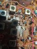
View attachment 47329
You can see where several "black" wires solder to a specific land area on the board.
Look carefully, there are some resistors and capacitors in this area
you'll see this area is also ISOLATED from Board ground and Case or Chassis grounds
- which has it's own "tie off" to the specific spot
- reduces noise and makes rewiring the mic easier.
MIC audio routes to here, filters, then heads off to Dynamike
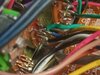
Your Pink wire - heads back by the Predriver - shown here...
So your Pink wire goes to a Resistor and Filter cap - both need to be there - it's how RF power can even get produced.by the Predriver.
So now you know how the radio's CB and PA switch works.
If you can't get any RF - then the PREDRIVER may have ben damaged and needs to be replaced,