• You can now help support WorldwideDX when you shop on Amazon at no additional cost to you! Simply follow this Shop on Amazon link first and a portion of any purchase is sent to WorldwideDX to help with site costs.

old Galaxy Saturn RF output bias circuit change (trash them MV1Y diodes)

BayouRadioAmplifier

Well-Known Member
Jul 5, 2022
170
174
53
66
I got this old Galaxy Saturn radio to bring back to life.

Working on the RF output. It had several watts of carrier for AM,
and SSB was "rough" "scratchy" sounding bad I was told.

did the usual RF output transistor bias level check at first.

at driver transistor TR44 the bias would barely change, and it was
around 1.8 Amps! so a problem here! It was due to the thermally mounted
MV1Y diode being open and not conducting, so all current through
the transistor base from this bias circuit failure.

at the two finals the bias would not adjust also. it was high.
found one of the thermally mounted MV1Y diodes to conduct
at .4 V, and the other at .8 V and also a 1 ohm "fuse resistor"
in a base bias line blown open. and while doing these tests, then the key-up
8.4 V transistor TR38 and diode D77 blew out.

so there problem in this bias circuit, on this radio, so with 8.4 V regulated
going to this circuit, a reliable bias circuit should be possible.
and looking things over, it was easy. it can be applied to these
other bipolar transistor RF ouput radios from RCI/Galaxy.

took out some parts, and got the 8.4 V key-up working again.
then put the following bias circuit in. got it biased correctly.
getting 10 Watts carrier with full modulation, and over-modulation
if wanted, and about 40 Watts PEP out in SSB.
..
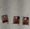
MV1Y diodes.jpg

cut out and remove these MV1Y diodes. trash them!
they did no good. made things worse!

Then put the screws back in transistors to heat sink rear panel.

..
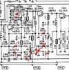
parts to remove.jpg
- remove these parts. You can cut most of them out.

..
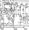
new bias circuit.jpg
- Make this circuit. put these quarter-Watt 680 (2), 470, and 100 Ohm resistors
in place. the "fuse resistors" R218. R216, R271 can be removed and by-passed also.

..
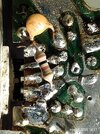
100 ohm R at driver.jpg
the 100 ohm resistor soldered to the bypass capacitor
that they forgot. it is not on the schematic. they added
it later. foil-side at circuit to the 2SC2166 driver transistor.
 

Was removing galaxy's attempt at negative peak control necessary for the simplified bias at the finals to work? Can you tell us about the journey that led you to yanking those parts?

This is me being legitimately curious because I have read Handy's Asymmetrical write-up on that section a dozen times and I still struggle with some of the wording he used. I wish he was still hanging out here.
 
  • Like
Reactions: Cable Guy
-- "Was removing galaxy's attempt at negative peak control necessary for the simplified bias at the finals to work? Can you tell us about the journey that led you to yanking those parts?"

You must be referring to diode D90 and capacitor C174.

this circuit is in most of their radios. I always rip out that
2.2 mfd. electrolytic capacitor in their radios. this capacitor
gets charged and discharged during AM TX. it adds a small
extra load to the modulator. not much of one. but it
could be a possible failure point.
there are plenty of smaller bypass capacitors on
the modulated voltage line.

that diode causes the bias voltage to the driver to drop
out when the modulation goes down .7 V below the voltage
at the junction of VR11 and R129. now that R129 is 470 ohms,
the voltage level there is higher. around a few volts.
there is no need to drop the bias here. the driver will still
conduct as in these radios with only AM/FM that have no
bias circuit. (class C/E)
not sure what they were thinking here.

in the old days of germanium audio power transistors there were
thermally mounted diodes for some type of protection and stabilization.
no need for that today with these rugged silicon transistors.
the newer radios do not have this done, as well as the higher power
external amplifiers using 2SC2290 as on RCI2995.

and, modulating the RF driver stage... that is another
line of thinking from years ago also.
 
  • Like
Reactions: Shadetree Mechanic
You must be referring to diode D90 and capacitor C174.

this circuit is in most of their radios. I always rip out that
2.2 mfd. electrolytic capacitor in their radios. this capacitor
gets charged and discharged during AM TX. it adds a small
extra load to the modulator. not much of one. but it
could be a possible failure point.
there are plenty of smaller bypass capacitors on
the modulated voltage line.

that diode causes the bias voltage to the driver to drop
out when the modulation goes down .7 V below the voltage
at the junction of VR11 and R129. now that R129 is 470 ohms,
the voltage level there is higher. around a few volts.
there is no need to drop the bias here. the driver will still
conduct as in these radios with only AM/FM that have no
bias circuit. (class C/E)
not sure what they were thinking here.
The page HandyAndy wrote suggested the function of D90 and C174 was to keep the collector from going below 8v. You say it pulls the bias down, his write-up said it holds the collector voltage up. I am trying to rationalize the two viewpoints because his seems to conflict with yours, at least how I read it anyhow.

If the modulation were below 0.7v, would having a circuit that lowers the bias in response be beneficial? That feedback loop is backwards. Lowering the bias in the presence of a weak RF signal during troughs in the modulation would result in distortion because that would feedback in a way that turns the transistor off, and cutoff is the thing we want to avoid here.

The AM modulator can source (conventional) current, but it cannot sink it, so I do kinda see that those parts could be holding the collector up a little like andy said, especially given the time constant of the RC network. He mentions that it results in the next stage running hotter though and a few other things. Its here somewhere.

EDIT:
I'm not saying you are wrong here, just asking. I want to understand it, but why on earth would galaxy have a circuit that cuts the bias on low signals? I gotta go to bed. I have a 2547 on the table that has been patiently waiting for an alignment, and while I'm in there, I will put a scope on both sides and see what its doing.
 
Last edited:
  • Like
Reactions: Shadetree Mechanic
-"function of D90 and C174 was to keep the collector from going below 8v."

if it did that, then the collectors on the other transistor collectors
would not go below 8 V, and it would not modulate correctly,
as is done with that "NPC mod" that I clip out of radios so they
get full modulation again. I was going to make a post on that.
 

Attachments

  • Like
Reactions: Shadetree Mechanic
-"function of D90 and C174 was to keep the collector from going below 8v."

if it did that, then the collectors on the other transistor collectors
would not go below 8 V, and it would not modulate correctly,
as is done with that "NPC mod" that I clip out of radios so they
get full modulation again. I was going to make a post on that.
Are you saying the DC blocking caps don't block the DC?

Even if the DC blocking caps were not there, 8v on the collector of one would not lead to 8v on the collector of the next. It would turn the next transistor on so hard that its collector would be at 0v, not 8v.

Is that video at the driver collector or the output? The reason I am pushing so hard on this is because galaxy and uniden each had a unique solution to the same problem, as I am sure other manufacturers did too, but you yanked those parts out like they were cancer, so I want to understand why. The initial waveform in that video, the ugly one, is on par with how handyandy described the driver collector. So that is why I wanted to know if that was the driver or the output. I would like to see, if you have it, a before and after at the RF output.

Thanks
 
Last edited:
I wasn't trying to be argumentative, What I got from Andy's page confuses me too. For example, passing that mess to the finals may prevent modulation pinchoff, but I would also think that makes an undermodulated mess at the finals just the same, so this isn't me vs. you, I'm not saying anyone is wrong, it's me trying to put two good sources of info together to understand the reasoning behind the implementation, and the removal, of those parts.

What I do know is that I have had a few galaxy radios with no problem achieving 100% modulation, yet those parts are still in the radio. So that begs the question, WTF is really going on here? lol
 
I think the final also being modulated has something to do with it since that modulation acts upon the waveform that the driver produced.

Is it possible that sending 100% modulation from the driver to the final is actually the problem since the final supply is also modulated? If the driver signal is at cutoff giving nothing to the final while the final swings to its lowest voltage, the transistor can turn off. And even if it don't reach cutoff, the positive peaks cannot exceed the amplitude of the negative peaks. It is symmetric.

With the "ass-hat mod" on, the peaks from the driver are a little higher and the troughs don't go below 8v, so when I think of 8v of RF being at the final's base for the negative half of its cycle (instead of decreasing RF or no RF at all being there), there is always a signal that can have negative modulation applied. It becomes asymmetric. Bigger positive peaks and regular negative peaks. So instead of both the driver and final pinching off at the same time, only the final is in a position to pinch anything off, and that also gives more control over the pinch-off in general and decreases the chances of pinchoff for strong audio peaks.

I know I am probably annoying a dozen people by now, sorry. When the theory seems plausible without violating the fundamentals of electronics, I feel like I am getting close to the correct answer. IDK lol
 
Last edited:
hey, yeah, brandon7861

just got on my computer this evening.
I knew what I did and said would get replies.
Messing with that "sacred" bias circuit.
I was keeping it short, and may not have explained
things properly. we are not arguing, it's all cool.
We will all learn something.

And then I sent that video I was going to post about
that popular NPC mod. So, I threw in a lot of confusion here.
I sent it all down a few "rabbit holes" (that is the expression
I hear all the time now!)

but that video is from the CRT display of the I.F. signal
on an old Motorola service monitor. So it is the signal
that a receiver will get. This radio has a diode soldered
at the modulation transistor. the NPC mod. I set
up an audio signal for full modulation. with the NPC mod
there is only positive going AM, and when the diode
(and on some radios a resistor with it) are cut out,
then you get full AM. you can see it on the scope, and
you can hear it in the speaker in that video.


I took out this NPC thingy mod on a few radios around here,
got the bias going right, and they love the results.

tonight I was offered two more old Galaxy Saturn radios,
but "basket cases" "un-repairable" that I can keep.
I know I can get them working, and add to all the
"junk" people give me.
 
  • Like
Reactions: brandon7861
- about that diode D90 in the Saturn.

Yesterday I was working on a RCI-2950 (013Z board) and it has
diode D93 in that same place. And with full negative going
modulation causing the voltage at the TP 7/8/9 shorting
board to go to zero, the bias going
to the RF driver to drops out, as expected, as observed
on an oscilloscope.

I also worked on a DX-939 yesterday, and the schematic
shows diode D93 in that place. but it is not on the board.
It would cause a real drop out in the bias voltage to the
IRF520 driver.
 
Thanks for checking that! Sounds like a few things are going on. Hopefully I can get into this 2547 this weekend, I want to play around in that area.


Write your reply...
dxChat
Help Users
  • No one is chatting at the moment.


      You do not have the permission to use the chat.