Thx!!! I just can seem to understand why I have 10.6975 at the non-IC side of C147 and noot at the IC side.....I will when I get home around 5am.
I really appreciate your help!
Thx!!! I just can seem to understand why I have 10.6975 at the non-IC side of C147 and noot at the IC side.....I will when I get home around 5am.
With my scope auto-scaling to 10v (because I have about 8v on that pin), the RF riding on the DC didn't show up well until I set the scope to AC couple which removed the DC offset and allowed the vertical space to be used for looking at the RF.Thx!!! I just can seem to understand why I have 10.6975 at the non-IC side of C147 and noot at the IC side.....
I really appreciate your help!


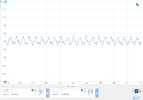
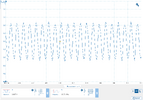
Ok, now we are getting into the deep and of the pool!!!! I'll do my best to keep my head above the water. I am measuring the frequency with my freq counter. It's an HP5335A. It does a great job but I believe that based on your information above it is likely that it is not sensitive enough for those readings. It also will not read the signal at TP 6 when aligning SSB so that is starting to make sense to me. My scope is a Philips PM3395 200MHz so I am assuming that I would see the same results as you with the ultra sensitive probe.That middle picture of the RF on the DC at the IC was done with the 10x probe setting, notice how the RF is barely visible due to the DC controlling the vertical scale. AC coupling the same 10x probe gets us a better picture of pin 3.
View attachment 72033
But even that looks terrible. So here is pin 3, AC coupled, using my homemade poor mans 1GHz active probe (BF998 version). Ignore the peak voltage, I added a little gain to that probe, the important part is that now it looks like a sine wave. The takeaway here is that even a decent 10x probe can really distort these weak signals.
View attachment 72034
It was this very board which made me realize I needed an active probe. My scope has a 200MHz BW and I thought the probes it came with would be good enough, but the signals around that 612 are so ridiculously weak that even looking at them screws them up. I couldn't get a FC lock to save me using the probes that came with my picoscope. I even tried those little 20dB amplifier modules on amazon, no luck. It wasn't until I made this active probe that I could get stable FC readings around that 612 in those galaxy radios. And that brings me to what should have been my first question. Are you looking for the signals with a 'scope or a FC?
I think at this point I am going to pull all of the parts in this area and test them. I will replace all of the easy ones like resistors and caps. I'll even throw the 612 from the 2950 in it. Then I'll test it out. One other thought. This is the radio that had a broken L3 inductor for receive which I replaced with a used one. I have tripple checked the install (solder and traces). I am unsure if that would have anything to do with this. I have looked at this in the schematic and do not see a direct correlation.I am at a loss, not sure what to do from here. That voltage being different has me scratching my head. You said you checked pretty much everything around it. Maybe check that electrolytic on pin 1 too.
I wonder if the balanced mod pot changes the voltage on pin 3 that much. Maybe if that setting is out of whack, these voltages will be too. Ill have to try that after work, heading out soon. Poke around with the 'scope and see if you can see evidence of signals, and if you have them, try to balance it and recheck the voltage on pin 3. Other than that, without it in front of me, I am stumped.
I don't see a correlation either.One other thought. This is the radio that had a broken L3 inductor for receive which I replaced with a used one. I have tripple checked the install (solder and traces). I am unsure if that would have anything to do with this. I have looked at this in the schematic and do not see a direct correlation.
Thanks!
