• You can now help support WorldwideDX when you shop on Amazon at no additional cost to you! Simply follow this Shop on Amazon link first and a portion of any purchase is sent to WorldwideDX to help with site costs.

Kinda like Christmas morning....

nomadradio

Analog Retentive
Apr 3, 2005
7,021
11,242
698
Louisville, KY
www.nomadradio.com
THE NEW PHONE BOOKS ARE HERE!

You can be excused if you don't remember that scene from the Steve Martin film "The Jerk".

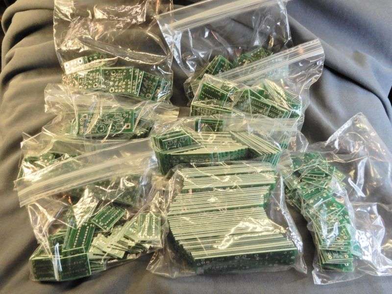
But that's how I feel every time the "OOPS" driver arrives with a new batch of blank pc boards.

But the real subject of interest is how to keep down the unit cost of small circuit boards. Any of these can be made on a piece of Rat-Shack style perf board. The labor to do it that way costs a lot more, naturally. That's the point of these boards. Reducing the labor to build stuff our customers keep asking for.

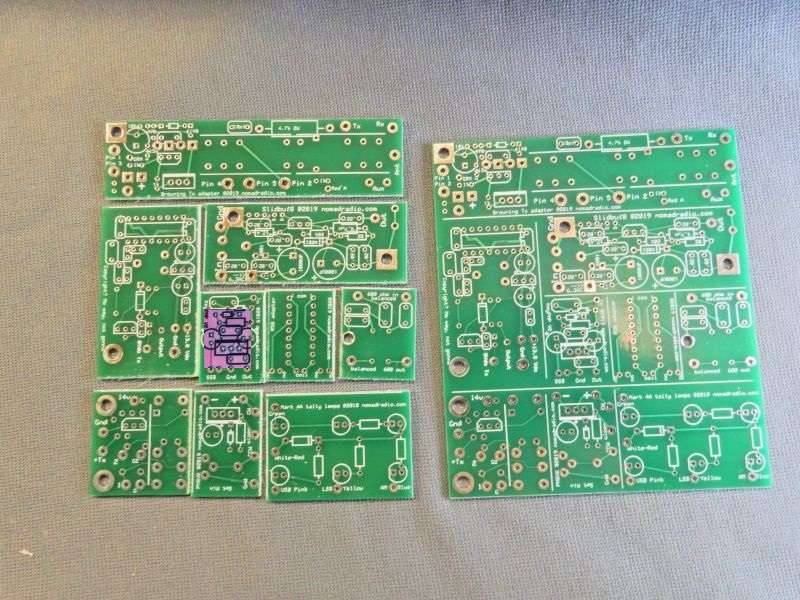
Here's how to keep down the item price of small circuit boards. Cram them onto one larger board, and cut them apart.

uOWTTu.jpg


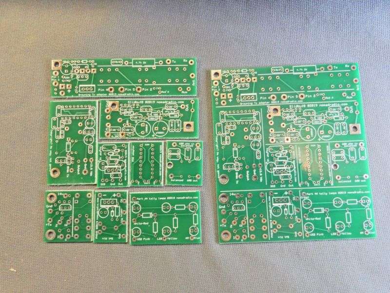
This does require eight cuts on our sheet-metal shear for each one, to get the nine gadgets separated. For 50 boards, that makes 400 whacks of the shear.

What was that about saving labor? Yeah, it's a boring exercise, but still less trouble than the perf-board method all in all.

Everything's relative.

Got ten done. 40 more to go. Or is that 320 more to go?

Still beats being the UPS driver who delivered them. At least from where I stand.

Gonna be busy getting 450 boards stuffed and soldered.

73
 

Never knew you could cut circuit with a sheet metal shear I figured it would break the green coating off the board. I learn something new every day.
 
First step after they're all cut is to build the "sample" unit of each, and get the parts for 49 more of that product into a sack for the assembler. Much easier to say "make it look like this one" than to write Heathkit-style instructions showing where each part should go.

One reason I don't sell build-yourself kits.

I'll reveal what each one does once there is a real sample with parts to show off.

73
 
Damn.

Don’t suck up the solder smoke, you’ll either be high like granny in the last Bevelry Hillbillies movie when they shocked her or you’ll be eat up with cancer.

 
As requested, here's one-ninth of the answer to "what are they for?".

This one gets built first because we ran out of them. Bad idea. Naturally this is the one I got asked about last week while I was waiting for the boards to arrive.

It's the one with the purple rectangle over it.

aHr5Dg.jpg


This is what it looks like assembled. It's the RF-keying circuit we use to replace the sorry versions we find in some old amplifiers. Biggest thing we use it for is in Maco and Varmint amplifiers that combined the preamp and keying circuit in one board. Removing the sorry-a$$ed preamp also gets rid of the original keying circuit. This one tends to perform better anyway, especially with the radio's carrier turned down.

gqWshT.jpg


The transistor's tab gets bolted to chassis ground, preferably near the "radio" coax socket. The 4.7k resistor goes to the center pin. A wire from the pad marked "out" goes to the relay coil. Couldn't be simpler. Unless you want a sideband delay. A wire from the "SSB" pad to the sideband switch, and the other side of the switch to ground takes care of that. Works fine with 12-Volt or 24-Volt relays.

The size of the transistor makes it pretty well universal. It will handle the coil current of even the biggest clunky relay. It's a darlington TIP125 transistor. Requires very little drive current to the base terminal to turn it on. Makes life easier for the two tiny diodes. They rectify a tiny sample of the radio's carrier. The tinier the better.

Here's a schemo from a few years back. The CAD I used didn't have a symbol for a darlington transistor, so I made my own. Looks a bit clunky but gets the idea across.

rfkeypnphy4.gif


The plan is to assemble all 50 of this batch and put it on Ebay. The Maco HV filter board we sell there has attracted questions about the preamp board for Maco 300, 500 and such. Not so much for the preamp, but for the keying circuit that was on it.
We'll see how that works out. Once these are all built I'll start in on the next-most urgent of these.

Film at 11.

73
 
Cool avatar! Don't hear much about Il Duce any more.

Let alone his original meaning of the term "fascism".

But I digress.

For years we have been making small pc boards like the one above and using them to support our repair operations.

Like this job.

quIOva.jpg


The keying-circuit board above gets priced at 18 bucks on a customer's repair invoice. Never did try to sell them on Ebay, The overhead of selling a single item there, plus the fees and postage almost doubles the price I have to charge. It's the economics of a retail-sales transaction. Makes a "cheap" item like that too expensive to sell.

Got all fifty of these keying-circuit boards built and tested, so I listed them on Ebay.

Have to price this one at 28 bucks to cover the transaction expenses.

Really never thought anybody would pay that much for something you can build yourself for around five bucks in parts.

http://www.ebay.com/itm/113649660788?ssPageName=STRK:MESELX:IT&_trksid=p3984.m1555.l2649


We'll see. Didn't risk much by listing it.

But the fixed cost of making a single-unit sale is pretty much the same to sell two of them or to sell five.

I also listed a quantity of two for 40 bucks, and a batch of five for 80 bucks.

That gets the unit price down to 16 bucks. Much more reasonable.

But only if you need five of them.

So I guess we'll see how this works out. Nothing ventured, nothing gained.

Next up is the "Peel-And-Stick Variable Key".

Film at 11

73
 
Two problems with keying the SB-220 this way.

First, the relay circuit has 130 Volts DC on it. This circuit won't tolerate nearly that much voltage. Don't know anybody who builds one that will tolerate a relay voltage that high.

Second, any amplifier that requires high drive presents a hazard to the receive side of the relay if you use this kind of keying circuit.

There will always be an arc across the receive-side contacts when they open up in response the radio's drive carrier. For a barefoot CB radio, this won't be much of a problem. Not enough RF voltage to do much damage.

But somewhere upwards of 100 Watts of drive power, this can become an issue.

Likewise, the transmit side of the relay will always exhibit "bounce". The contacts on the transmit side don't make contact all at once. They will briefly make and break contact because of the spring action built into them. This bounce process is over pretty quickly, but the tiny gaps that open up for a millisecond or two with each bounce also cause a tiny arc. The higher the drive power, the sooner this wears out the transmit-side contacts. Worst case is to spot-weld the transmit-side contacts together, so the relay really does "stick" until you pry them back apart.

Keying the amplifier from a ham radio's 'accessory' socket gives the amplifier's relay a head start, so that there is no energy on the receive-side contacts when they open up that gap while changing to transmit mode. And the risk of arc damage during the (short) bounce interval is also reduced. Keying the amplifier (in effect) from the mike switch gives the amplifier's relay a head start. Ideally, this allows that short bounce interval to pass before the radio's RF power arrives at the relay.

This is a problem we see over and over using a foot switch with high-drive amplifiers. The proper protocol is to press the foot switch BEFORE keying the mike, and releasing it only after the radio is unkeyed.

But folks who are sloppy about this show up complaining that the relay is "sticking", and won't let the radio receive when the mike is released. What's really going on is that the receive-side contacts are toasted and oxidized from the driver's RF energy, either keying the big box late, or unkeying the amplifier early.

For that reason we recommend taking the money you would spend to put a carrier-sensing circuit into the SB220 and spending it to have a relay installed in the radio, with a keying jack on the rear of the radio. Costs roughly the same to modify the radio as the amplifier. Probably less. A patch cord to the amplifier now eliminates the foot switch.

And the problem of burning out the relay's receive side once a year or so.

In all fairness, the drive level for a SB220 is on the threshold where the RF arc causes trouble. A 25-Watt drive carrier probably won't cause this problem too quickly. Bigger boxes with four, six or more 3-500Z tubes should NEVER be activated with a carrier-sensing circuit. That's the size amplifier that gets relay damage the fastest by sloppy foot-switching.

But what you asked is "could" this be done. Taking this board, putting it in a box with a 12-volt relay, and powering it with a 12-Volt wall wart would do the job. There is no handy source of low-voltage DC in the SB220 that can be 'borrowed' to run this setup.

But the labor to build any simple gadget into a box, wire up the coax sockets, relay-keying cord and power supply will get you a gadget they used to call a "hotfoot" box. Would push the price above 100 bucks, unless you built a buttload of them with really cheap labor. Putting that relay inside the radio is cheaper.

Just shows the difference between "could" and "would".

73
Thank you for the excellent explanation.
 

dxChat
Help Users
  • No one is chatting at the moment.