• You can now help support WorldwideDX when you shop on Amazon at no additional cost to you! Simply follow this Shop on Amazon link first and a portion of any purchase is sent to WorldwideDX to help with site costs.

Ameritron ALS-500M HF Solid State Amplifier Review

Moleculo

Ham Radio Nerd
Apr 14, 2002
9,194
1,674
283
I've owned the Ameritron ALS-500M with Remote Control for a few years now, so I figured it was time to write an article about it. This amplifier is for 10-160 meters and uses four Toshiba 2SC2879 transistors to provide a maximum power output of 500 watts. The 10/12 meter option is an extra $30 that you can install yourself. With the optional remote, the total package is just over $900.

The amplifier is intended for mobile installations and is expected to be used at voltage supply levels between 11 and 18 volts. Ameritron says that the unit will achieve the rated output power at 14 volts.

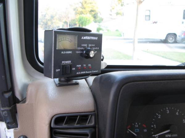
Before going into details about the amplifier installation and tests, I'll show a few pictures. Here is one of the amplifier face and the remote control unit:
1531-1294015326-1f351acaa87714d2c4cfe23e4c2e3839.jpg


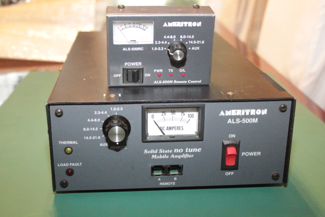
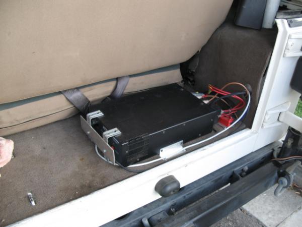
The main amp weighs only 7.5 pounds and is 3.75" high x 9" wide x 15.5" deep. The relatively small size is one of the main reasons why I chose this unit, as fitting any thing behind the seat in my small Jeep is a major concern. This fits perfect, as you will see in later pictures. The remote head is about the size of a deck of playing cards. You can see from this picture how the basic operation is performed. A band switch is used to select the proper output filter; the AUX position is used for 10/12 meter operation. If you're going to remote switch the amp, you set the dial on the amp to REMOTE and leave the power switch ON.

The THERMAL indicator is triggered if the transistors over heat and tells you that voltage for the transmit relay and bias voltage for the transistors has been removed until the temperature drops to a safe level. I've never personally witnessed this condition with my own amplifier. The LOAD FAULT indicator is triggered when band switch is in the wrong position, the antenna SWR is too high, or the amplifier is being over driven. When this happens, you simply turn the amp off and on to reset. This is basically a protection circuit to help prevent you from destroying the PA transistors.

Lastly, the ammeter indicates the current draw of the transistors collectors. I don't what this is good for except to indicate that the amplifier is working properly. If you don't see any needle movement while transmitting, it's not working. Further, I'm not sure that this meter is terribly accurate, either. Personally I think it would be more useful if this was a volt meter since I would rather know what voltage is being supplied to the amp in a mobile environment.

Here is a partial shot of the rear of the amplifier:

1543-1294015811-67e7e1e49b3f3fddff6c247f2f46a778.jpg

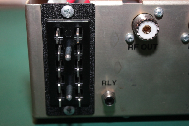
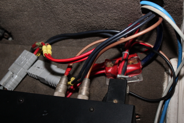
The large set of terminals on the back is the power harness. The supplied power harness has two 10 gauge positive and two 10 gauge negative wires, as well as a small positive wire that should be attached to a switched power source. This small switched wire is intended to turn the amplifier's power off when the vehicle power is off.

One of the first things I noticed when I popped the cover off is the input swamping network:
1532-1294015326-6031ae5a580cd73f159c88f14f22b569.jpg


This network helps ensure that the transistors are not over driven to a point of saturation, which is important in keeping the output as linear as possible. It also helps protect the transistors from accidental overdrive which could destroy them when using AM, CW, or other carrier modes. One important point is that this swamping network will not guarantee a linear output signal; it is just a step that assists the process. If you severely overdrive the amplifier or have a non-linear signal input, this stage isn't going to clean things up for you. It's still a nice touch, though.

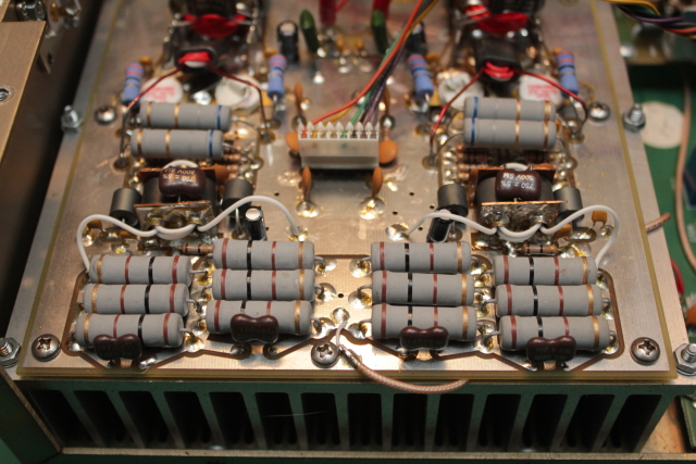
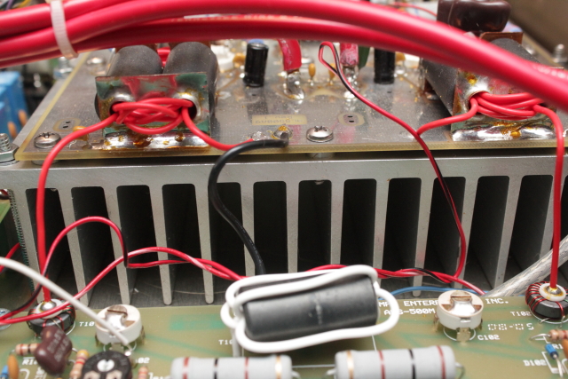
Here is a close-up picture of the main Power Amplification deck using the Toshiba 2SC2879 transistors:
1533-1294015326-48a9572f83be10625dccd231f8cec4b0.jpg


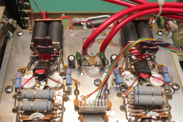
I'm nowhere close to an amplifier design expert, but I can identify a standard push-pull configuration using bipolar transistors when I see one. You'll notice that one of the transistors in each pair has a diode across them that is smothered with thermal grease:
1541-1294015553-d0450ecd2e18dc278e857831e650d86b.jpg

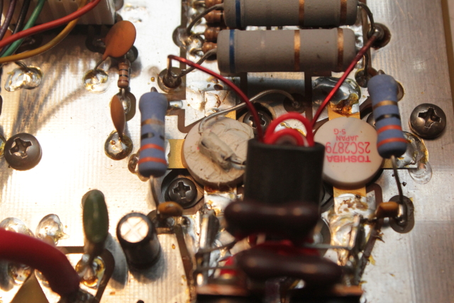
These diodes track the transistor temperature, causing a voltage change that is monitored at the bias board which not only causes it to supply an appropriate level of bias voltage to the transistors, but also triggers a Thermal Overload condition if necessary.

Speaking of the bias board, here is what it looks like:
1538-1294015433-ee6e925605de8245150519a6046356d1.jpg


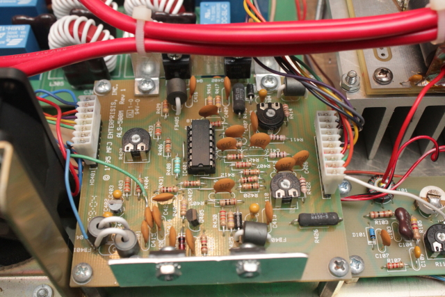
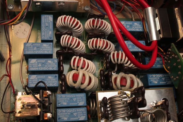
In addition to regulating bias voltage supplied to the transistors, this board also controls the cooling fan, turning it only only when necessary. It contains the components that work with a circuit on the Combiner board that detects the load SWR to trigger a LOAD FAULT if necessary. Here is a pic of the combiner board which takes the output of each PA section and "combines" them for the output stage:

1537-1294015433-33799e34cd3b26cc736840744de29800.jpg


Here is another picture which shows the PA board sitting on top of the fairly large heat sink with the combiner board down in front:
1540-1294015553-71bedbdb78dd496f0f3664b4622d32e5.jpg


This is the exhaust fan that sits beside the bias board:
1539-1294015553-3538b67088b0031e78a652e68904cd4f.jpg


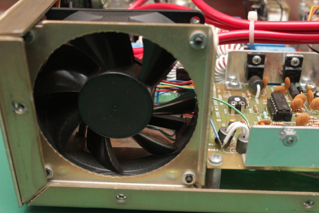
I've never experienced a situation where this amplifier ever triggered a thermal overload condition. The size of the heat sink, fan control, chassis design, and thermal tracking bias design all keep things running as they should.

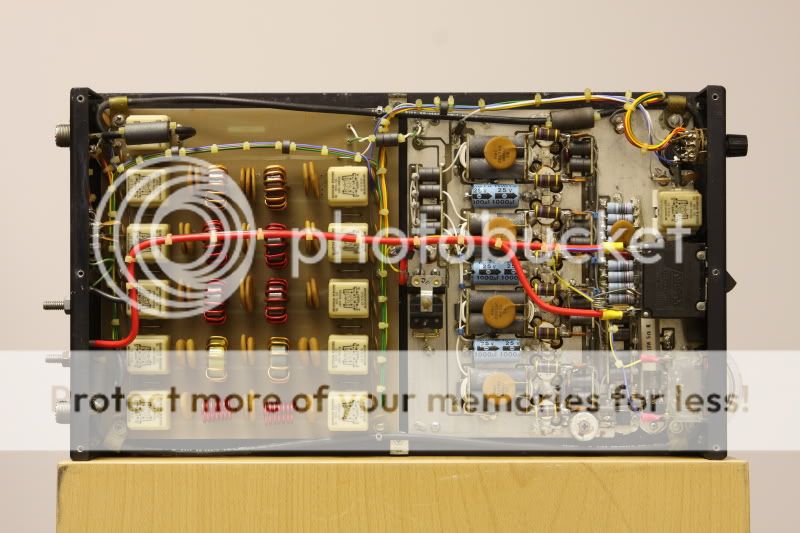
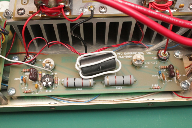
The output filtering is accomplished using 5 pole filters on this board:
1536-1294015433-6e6810a175d487b66fdd7cd5485c8efa.jpg


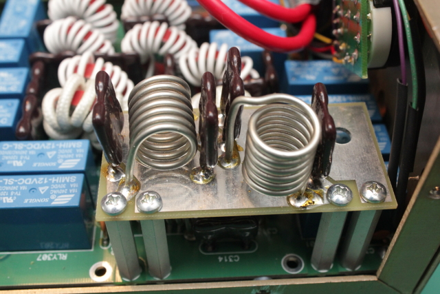
If you want to use the amp on 10/12 meters, you must purchase the MOD-10M option, which is basically just the appropriate output filter that also enables the amplifier to transmit on these frequencies. It is easily installed on supplied posts over the filter board and looks like this:

1535-1294015433-5370ada7c621f56cd19fad00020f12fb.jpg


Next I'll briefly discuss my installation details and then chart my own tests on the power output capabilities of this amplifier. If you have any of your own experiences or tests of this unit, feel free to contribute.
 

Documentation and Installation

In an industry where most Instruction Manuals leave quite a bit to be desired, the ALS-500M is a refreshing change of pace. This amplifier's manual provides adequate description on the function and design of all of the major circuits, the affects of various input voltages on the performance, and how high the amplifier behaves when the expected SWR level is exceeded (at 70 watts of reflected power, the internal SWR protection circuit disables the amp).

Installation instructions are very detailed. They discuss everything from location, power supply requirements, voltage drop of supply wire used, fuse considerations, auxiliary batteries, to grounding of various types of vehicles. Power and rig connection diagrams are included along with complete instructions on how to operate the amplifier and what to do if various fault conditions are encountered. Ameritron has done everything possible with this manual to ensure successful installation and usage.

The last pieces of info included in the manual are circuit schematics and parts lists for each board. This is absolutely outstanding, in my opinion. Ameritron makes no secret about how this amplifier is designed, and by providing the complete schematics makes it possible for any technically inclined individual to troubleshoot problems they may encounter. I suppose someone could even copy the design and order the parts directly from Ameritron if they wanted to do a homebrew project.

If you want to download a copy of the manual to view for yourself, Ameritron has posted it on their website here:
http://www.ameritron.com/pdffiles/ALS-500M.pdf

My Installation

Installation in my Jeep Wrangler was fairly straight forward after a little planning. The included lengths 10 gauge wire and inline 30 amp fuses were not going to cut it for me because I wanted to install the amplifier in the back of my Jeep without an auxiliary battery. I went to the local auto parts store and picked up a car stereo amplifier hook-up kit which included plenty of 4 gauge fine stranded wire and an inline 60 amp fuse. It also included a distribution block which worked out perfectly to attach the amplifier's power harness 10 gauge wires to.

I ran the 4 gauge wire through the frame and up to my Optima Yellow Top battery where I mounted the 60 amp fuse:
1548-1294195858-570433951df7d8f5c53b23d8425adb38.jpg

The frame of my Jeep is well grounded, so I didn't need to run additional ground wire. I just attached the ground wires to a nearby bolt that attached to the frame. Did I mention that I have a 200 amp alternator in my Jeep to power the winch and other accessories? Coupled with the Optima battery and 4 gauge wire for the 10 foot run, I don't have any concerns about powering this amplifier properly. I mounted the amplifier in the back and attached all of the cabling and wires. The remote cables and transceiver interface run under the vehicle carpet while the power and antenna connections run through the body. I attached some spare Anderson Power Pole connections to the wire harness for quick disconnect in case I want to use the amplifier elsewhere. Lastly, I made a small face guard bracket with some longer chassis screws to help keep the amplifier face from getting damaged by all the stuff I pack back there. Here is a picture that shows the wiring, including the distribution block. It looks a little messier than it really is, but that's what happens when trying to squeeze these things into a tight location:
1549-1294195858-0babe4c84e7e413e185793d4ee81793a.jpg


Here is a picture of the completed installation behind the rear seat:
610-1249008333-62c1f3fb5a7f3699fc5c25e420b021d7.jpg


I found a small cell phone / gps mobile mounting bracket and adapted it for the remote head installation. Here is the remote located up front:
614-1249008333-70571c9bd1eed3c4c36c48b3baab0c98.jpg

It works great!

Lastly, I ran a small relay cable from my Icom IC-7000 (previously a IC-706MKIIG) to trigger the amp.

Remember, when you install an amplifier like this, you MUST make sure that your antenna is capable of handling the resulting output power. There are plenty of choices available, but don't try this with hamsticks! :eek:
 
  • Like
Reactions: Darkrfoverlord
Power Output Tests

Now for the part that I'm sure everyone is most interested in: what does this thing put out? I have a big enough power supply to test this on the bench, but I wanted to show what it can do in a mobile installation for purposes of this review. The amplifier is rated for 400 watts CW, and can reach 500 watts on SSB peaks. The numbers below were measured with a Bird 43P meter using 50, 100, 250, and 500 watt elements while the antenna was replaced with a 2KW dummy load. The Jeep was left running at about 2500 RPMs to ensure that the 200 amp alternator was able to deliver plenty of current. These tests were done in CW mode using a steady tone from the transceiver. On each band I set the transceiver power level using the smallest meter element necessary and then tested the amplifier output after switching to the appropriately sized slug. Each band was tested using 5, 10, 25, 50, and 100 watts of drive.

Here are the results:
Band/Drive | 5w | 10w | 25w | 50w | 100w
1.9Mhz
|80w|140w|360w|425w|425w
3.9Mhz |70w|140w|310w|410w|410w
7.2Mhz |90w|160w|350w|410w|450w
14.2Mhz |85w|150w|255w|320w|360w
18.1Mhz |70w|130w|225w|270w|300w
21.2Mhz |60w|110w|180w|210w|240w
24.9Mhz |90w|150w|240w|280w|310w
28.5Mhz |80w|145w|260w|320w|370w

On the lower bands, less drive was required to reach maximum power output. For example, on 160 and 75 meters, only about 35 watts of drive were needed. As the bands progressed higher, more drive was required to reach maximum output; about 70 watts was necessary at 20 meters and above. The dip in output power between 18 and 25 Mhz is interesting and I'm not sure how to explain it. Perhaps the output filter for that frequency range needs to be tweaked slightly?

Regardless of the power dip in the noted bands, the low bands are where you need the amplifier the most and the power output is certainly there. You get a pretty healthy power boost for the others bands, as well. In summary, you can expect to somewhere between 5db-6.5db gain in power output from this amp which should be good for about 1 S unit. In a mobile environment coupled with lousy band conditions, that 1 S unit may make the difference between being heard...or not.
 
  • Like
Reactions: Darkrfoverlord
...Remember, when you install an amplifier like this, you MUST make sure that your antenna is capable of handling the resulting output power. There are plenty of choices available, but don't try this with hamsticks! :eek:

I just got off the phone with someone at the Lakeville Hamstick website phone number and was told they are good to 600w pep! (y)
 
I just got off the phone with someone at the Lakeville Hamstick website phone number and was told they are good to 600w pep! (y)

That's with a perfect match and 1:1 SWR. Running 400 watts into an antenna rated for 600 watts is tricky enough but throw in a little SWR and watch that antenna become a tesla coil in short order. Some guys will run a 600 watt rated 20m hamstick on all bands with a tuner and 100 watts and they still burn them out. I ran a 20m hamstick just that way until I noticed bad heating in the coil and that was with just 100 watts but running it off resonance where the SWR was unholy.
 
Before I could afford a Screwdriver I ran Hamsticks, only Lakeville the original, never Ironhorse or any others which seem flimsy to me by comparison.

Yes, I did keep a small standard screwdriver in the glove compartment for adjusting them depending on where on the band I was talking. It was a hassle but I did surprisingly well with my ALS-500 until I got tired of such a large amp and let it go to a local HAmateur.

I never experienced more than warming of the 80m Hamstick. I saw about 450w pep on mine on 80m driven by a Yaesu FT-100D @ ~80w drive.

I had it rooftop mounted on a 4-magnet mount with a solid ground from the magnet mounting plate to my roof directly beneath it where a rack screw allowed me to make ground connection. I used a Hustler quick-release for easy swapping.

I even surprised Art Bell once with a 25 over from the parking lot of "Orv's":blink: near Williams, Ca. using an 80m Hamstick behind my earlier Icom IC-735 & ALS-500 combo.
 
Ive actually thought about getting one of thes ALS-500 I like my other Ameritrons and have had a few of these ALS-500 come my way for pretty good prices and I often feel like wrappin myself in the head for not grabbing one :(
 
I just got off the phone with someone at the Lakeville Hamstick website phone number and was told they are good to 600w pep! (y)

That's good to know. I have swap meet knock-off hamsticks that are only rated for 200 watts.

Surely you'd prefer to have a Metron in the trunk?

I passed on one of those a few years ago at a hamfest that was in real nice condition. I probably should have purchased it, but he wanted a bit much. Actually, he wanted more than a brand new ALS-500. There is something to be said, however about being able to get tech support for a product because the company is still in business.
 
Surely you'd prefer to have a Metron in the trunk?

So much neater back in the 80's. Who needs all that untidy wiring anyway.


Here's one of my two. I still have one brand new in it's 20year+ old box.


Metron3.jpg


Unit 148
You must be a mind reader... that's exactly what I replaced it with. I bought an IC-706IIG and hated it in comparison to the FT-100D so I put it on ebay and got a NEW-IN-BOX Metron for it.

Got 775w pep from the Metron.
 
Harmonics and Intermod Products

No linear amplifier review is really complete without some discussion on the the harmonics and intermod products introduced by the amplifier. I don't personally have the equipment to measure this, but I have consolidated some information on the subject published by G3SJX.

The following table shows both 2nd and 3rd Harmonic output levels, as well as Intermod products using a 2-tone SSB test. These test numbers are for an amplifier output level of 400 watts max. Note that 21Mhz is missing intermod metrics because he was not able to achieve 400 watts of output on that band with his test amplifier.

FREQUENCY | 2nd Harmonic | 3rd Harmonic | 3rd Order I-mod | 5th Order I-mod
1.8 MHz|-52dB|-56dB|-30dB|-50dB
3.5 MHz|-51dB|-57dB|-30dB|-47dB
7 MHz|-65dB|-55dB|-28dB|-48dB
10 MHz|<-70dB|-62dB|-28dB|-42dB
14 MHz|<-70dB|<-70dB|-24dB|-42dB
18 MHz|<-70dB|-66dB|-24dB|-42dB
21 MHz|<-70dB|-68dB|n/a|n/a
24 MHz|<-70dB|<-70dB|-25dB|-40dB
28 MHz|<-70dB|<-70dB|-24dB|-42dB
 
  • Like
Reactions: Tallman
Summary

I've had this amplifier in my Jeep Wrangler for several years now and it has been reliable. The SWR and band protection circuits really do work well, but it requires that you have a pretty carefully tuned mobile antenna system. In my case, I had to tweak my matching system for 80 meters to make everything happy.

In my Jeep, I've done practically every type of off-roading, from mountain trails, to rock crawling, and bouncing around in the desert. Everything gets rattled around and shaken. Despite all of this, the amplifier has held up and I've had no component breakage. The only part I've ever replaced was the remote meter panel because it yellowed over time from the sun. The replacement was done merely for cosmetic purposes; it was working fine.

I did have one problem that developed where the amp would key, but not draw any current and not produce any power output. This problem turned out to be caused by a faulty remote head cable (cheap CAT 5) that needed to be replaced. I guess over time one or more pins in the RJ45 on the cable had developed an intermittent connection. Replacing it with a better quality, more durable cable solved the problem.

So in summary, the ALS-500M amplifier has proven to be durable enough to be used in a rugged environment. The power output is as advertised, although the numbers drop off a little on the higher bands. The remote head is small enough that you can trunk mount the amplifier and it has all the features needed to help keep you from blowing it up :eek:. The 3rd order intermod performance is adequate for mobile use, but you might want to consider a different amplifier to use in a base installation.

As a whole, I'm pretty happy with this amplifier especially considering the space I am constrained with.
 
  • Like
Reactions: Darkrfoverlord
I think some of you guys must have mental health issues. Why on earth would you compare a product designed and marketed to Ham radio operators. I mean seriously why would you make such a illogical and poorly conceived argument for an item by comparing it to an illegal product not designed for Ham's? I understand what an inferiority complex is and have to wounder why you guys feel so inadequate that you have to make such silly comparisons. Maybe we can compare a Ham gear to commercial and military broadcast gear that would be just as pointless, illogical and ill conceived. Traditionally Loser and Bullies compare themselves to other's that they know are clearly not on par with themselves this makes them feel all good warm and fuzzy inside about themselves as they collectively pat each other on the back!Real men compare themselves to those that are better then they are so they have something to aspire to something to drive them to greatness!

Personally I would ashamed of myself collectively as a group if all I did was whine about people I think are bellow me and sat around pointing out how great I am and how great the gear I buy is!!!LOL

You are supposed to set an example for those that are bellow you to aspire to I do not want to be like anyone that has to get a collective group hug by putting other people and products down in order to feel good about themselves or to justify any purchase they may make.

I think it is stupid to put 100 watt's into a design to get 300-450 watt's back out. All the stuff that is in this design that is not on a Texas Star 667 or 500 could be added easily. Some of it is not even needed and is of dubious good to begin with.The basic RF deck is not anything significantly new. WOW 4 BIPOLAR 2sc2879'S what a clever idea I wonder why no one else thought of that....Oh yeah that is right that idea has been in the CB world for over 2o year how nice for Ameritron to make it late to dinner! For what they charge for the product it should be auto-tuned and work on 120V and 12V. Plus it is huge you could fit 2 TS667's in the same space it takes up. So it had better have a lot more parts in it for it's size. I am guessing I could by a 16 transistor Texas Star for what thing must cost. Since unlike most Ham I can actually use a soldering iron and can read and understand the ARRL Handbook I could add most of this to any decent solid state amp on the market.

On top of that most of the reviews I have read on eHamreviews has been very negative about this product. Ameritron as usual has had quality control issue's and less then spectacular customer service. Many of them are not putting out the power they should either. DO not take my word for it go read all the reviews.Best part is that Texas Star does not use any surface ount parts so I can work on them. If you look at the 10/12m tuning circuit notice the cap is SMD to a small silver coil. Their are other smd's in this unit too which means should it break during a National or Local Emergency you will not be able to fix it on your own more then likely.

I do not though think the power input required to get such meager output is worth it not at the dollar per watt output. You could take an auto-tuner board insert it in a 4,5,6,8,12,16 transistor Texas Star and have a very similar end product with more output for every watt input if you remove the swamping circuit from them.

I still hold that if you want to compare Ham gear you need to compare it to the best out their so broadcast gear and military gear not illegal gear designed for price point sales to those that know little to nothing about RF circuits. Aspire to greatness not to be petty thugs!
 

dxChat
Help Users
  • No one is chatting at the moment.
  • dxBot:
    Tucker442 has left the room.
  • @ BJ radionut:
    LIVE 10:00 AM EST :cool:
  • @ Charles Edwards:
    I'm looking for factory settings 1 through 59 for a AT 5555 n2 or AT500 M2 I only wrote down half the values feel like a idiot I need help will be appreciated