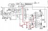
• You can now help support WorldwideDX when you shop on Amazon at no additional cost to you! Simply follow this Shop on Amazon link first and a portion of any purchase is sent to WorldwideDX to help with site costs.

RM Italy KL-503 Lost Bias?

Yes, its the S45HP, with the RFX75. Its likely damaged from all that power, yes. Yes, I see exactly what you're saying, but no, it wasn't me, I don't drive the piss out of my boxes like that.
This was given to me, and now I'm trying to fix it so I can keep it on the side as a spare. No, it won't ever be driven by that much power in my hands, the "hottest" radio I have is my 979, and soon a 2950.


Now that we got that straight, have your friend run the S45 barefoot into that sweet sixteen. 60-80 watts should make her sound real good.
 
I looked but, could not find a 1 X 4 RM-Italy Amp, here is a roadmap for a straight 4 transistor amp. In the colored in area, you will find the bias components, at the base of the input x-formers, there should be .6 vdc. There are 2 transistors, TR5 and TR6 as well as diodes which form a voltage diver and a regulator system.

Work back from from L9 and L6, D17, D18, D19. R13 has source voltage from Vcc.

.
 

Attachments

  • amp-rm.jpg
    amp-rm.jpg
    111.3 KB · Views: 238
KL-503 is a different critter from the 500.

The 503 is all fet finals. While I have not seen a schematic for one yet, most other manufacturer's use a regulated five volt then resistor divider network to get the bias to where the FET's operate in the proper area of the transistor's specification for the amp they have designed. Look for a regulator circuit like a 7805 or the European equivalent. Also check your traces and feed through, and look for wires with insulation of the transformers inserted into the solder joint. I have rebuilt so many of the KL-500's and it usually came down to a quality of construction problem.
Most of the time it was a customer abuse problem with OVERDRIVE as the number one cause of failure. I really would like to see the schematic of the KL-503, They always put a schematic of the unit in the box, do you still have yours?
Sorry about the book!

So which is it, you first said," I have rebuilt so many of the KL-500's and it usually came down to a quality of construction problem."

Then you turned around and said this," Most of the time it was a customer abuse problem with OVERDRIVE as the number one cause of failure."

The RM amplifiers are low end low drive light duty amplifiers. I guess maybe it could be a combination of the two issues you listed. Maybe that was what you intended on saying.

In this example the S45-HP radio just plain overdrove the piss out of that amp. I would sell it on E-Bay as a fix or repair and be done with it. Chaulk it up to a lesson learned.
 

dxChat
Help Users
  • No one is chatting at the moment.
  • dxBot:
    Tucker442 has left the room.
  • @ BJ radionut:
    LIVE 10:00 AM EST :cool:
  • @ Charles Edwards:
    I'm looking for factory settings 1 through 59 for a AT 5555 n2 or AT500 M2 I only wrote down half the values feel like a idiot I need help will be appreciated