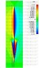
Now I see what you're getting at Bob. I think I may have some of the answers too. The way it was explained to me is that individual currents can be seen by the colors on the respective elements themselves while the combined pattern can be seen as the radiation propagates away from the element and the individual shades of color blend together moving outwards.
It was also stated that the individual currents displayed on the cone radials are divided by the number of radials and the mast. All of which radiate in a constructive phase. Which makes each radial appear weaker than the vertical radiator while the combined field from all radials is significantly stronger then what is displayed on any one.
That was explained to me at the same time the CST models were given to me. After looking at it more, I noticed some interesting things. The loop has been omitted. I believe this was done for clarity since it is a known fact the loop does not alter the performance noticeably.
I also think 2 of the 4 radials have been omitted for the same reason. One would be out of view from behind and the other would be covering the main radiator. If I'm correct then each radial is only supporting 50% of the total currents. This too should not make a significant difference in the total field.
Since I noticed these things long after the project I was working on was completed, I did not reopen the discussion with the engineer at Sirio. I'd really like to find someone else with CST willing to experiment further. I've already asked a million questions from my source and don't intend to wear my welcome out.
Bob, after watching the CST video a little more I spotted something I missed in the original still photo. I believe I can now see the separate opposing currents forming on the inside and outside of the cone. If you look carefully, just as the phase flips and before the currents ramp up, you can see the inner portion of the cone matching the color of the vertical radiator before the currents get strong enough to combine and look like one inside the cone.

")