• You can now help support WorldwideDX when you shop on Amazon at no additional cost to you! Simply follow this Shop on Amazon link first and a portion of any purchase is sent to WorldwideDX to help with site costs.

$3 For Better DX-959 Stability?

Robb

Honorary Member Silent Key
Dec 18, 2008
11,432
3,651
323
Silicon Valley CA, Storm Lake IA
Intro:

Got pretty tired of this radio taking so long warming up and being so far off freq, so I thought I would experiment a little bit with it. If you have ever owned one - and perhaps still do; then you must know what I mean here. Going to share my notes here so that there is a record of what transpired. I'll keep it to the point.

Mind you, I wouldn't call these mods a cure. I might perhaps call it a noticeable improvement, and I would also call it cost effective. Keep in mind that the point I am making here is that I just explored two avenues of approach to the problem. I would also call it a starting point, so anyone wanting to pick up where I left off; then no one would be more pleased than I.

None of these parts are expensive if you have some parts radios lying around and you have all of the correct values; but that is unlikely. You will find some useful values in junk radios, just not all the ones you will need. When first setting out to do this, the biggest problem faced was finding the vendors that have the parts. If you find/buy them online, you might pay 3X-5X what I had to pay. Fortunately, living in Silicon Valley does have some perks. One of which is having a few places that still carry a wide variety of electronic components. I bought 80% of the parts new and then scavenged old radio carcasses for the rest.

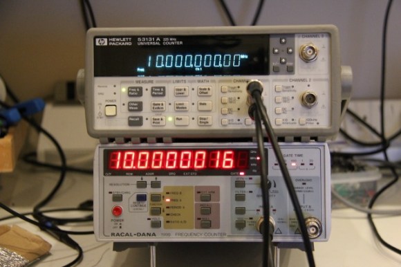
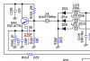
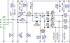
There are four oscillator circuits in this radio: the reference oscillator that works directly with the PLL chip linked with the voltage controlled oscillator, loop oscillator, and the carrier oscillator. If just one of these oscillators move off freq; the radio will experience drift. Usually this drift is normal in a radio that is warming up. Some radios have less, and then there are radios that have more; the Galaxy 949, 959, as well as other radios that use the EPT069610Z chassis in particular. Includes a couple of Ranger radios too, such as the 696 Freedom 1 that uses a very similar chassis. There are also spin off chassis in the 10m Galaxy radios that have the same problem with drift.

The Problem:

Going on the assumption (yes, I know) that capacitors (as well as a couple other key components, such as coils and resistors too) tune oscillators, and that capacitance will change with temperature, and this stray capacitance adds/subtracts from a stable state; then to improve the oscillator tuning capacitors would be the most logical place to start.

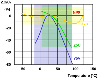
Most of the caps that were replaced in the radio's oscillators have a 'UJ' suffix. The UJ caps are - by far - not as nearly as stable with temperature change as the NP0 are. Not any where close - matter of fact. The mfr choices for using a poorer grade of parts in this radio has proved to be the cause of this drift issue - IMO. But there is another part/other aspects that affect drift which will be dealt with later on. Since these UJ caps used in production of these radios are found in key points of the many oscillator circuits, they seem to be the most likely culprits for causing drift. And - therefore - the ones that were chosen to be changed out with better caps.

From Wikipedia:
Class 1 ceramic capacitors are accurate, temperature-compensating capacitors. They offer the most stable voltage, temperature, and to some extent, frequency. They have the lowest losses and therefore are especially suited for resonant circuit applications where stability is essential or where a precisely defined temperature coefficient is required, for example in compensating temperature effects for a circuit.

Class 1 capacitors have a temperature coefficient that is typically fairly linear with temperature. These capacitors have very low electrical losses with a dissipation factor of approximately 0.15%. They undergo no significant aging processes and the capacitance value is nearly independent of the applied voltage. These characteristics allow applications for high Q filters, in resonant circuits and oscillators (for example, in phase-locked loop circuits)
Ceramic capacitor - Wikipedia, the free encyclopedia

The Parts:

The two areas addressed here were the capacitors and the resistors. Certainly the tuning coils of the loop oscillator are responsible for the residual drift. Even the 1N4148 diodes in that circuit add stray capacitance when warming up.

These parts I chose are not exactly off-the-shelf items. Not exactly easy to find, but with little effort you can duplicate what I used with some time shopping online. Or, perhaps you have a supplier nearby if you live in a large enough city/town that carry these NP0 grade caps. Mouser Electronics has most of them - BTW.

http://in.mouser.com/Passive-Compon...itors-MLCC-Leaded/_/N-bkrdj?P=1yzt48aZ1z0x7lp

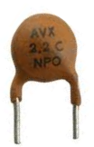
The capacitors chosen for this experiment are mostly NP0 (that's 'N-P-Zero') caps, along with some close-tolerance MLCC/monolithic caps that do not share the same tight tolerance in regard to temperature/capacitance stability as the NP0's. Reason is, I simply could not find all of the NP0 caps that I would have liked to.

Ceramic NP0
NPO-ceramic-capacitor.PNG

Monolithic X7R
inhouse_ck05bx471ktr1_t.jpg


Temp vs capacitor stability:
330px-MLCC-Cap-Temp-Klasse-2-Kurven-engl.svg.png


Part 2:
Tomorrow.
 

Attachments

  • dx959 cap mods for ssb stability 1.gif
    dx959 cap mods for ssb stability 1.gif
    213.4 KB · Views: 153
Last edited:

Note:

First of all, I don't want to give any hobbyists the impression that by merely replacing the caps/resistors that their radio will work better. It will not. If one just replaces the caps and resistors as mentioned, the radio will be off freq. Perhaps way off freq. Probably.

Anyone attempting to do these mods will need to have a bench freq counter to re-align the radio's oscillators. Using the aftermarket plug-in counters designed for particular radios will not work either. Neither can you use the 959's freq counter, as these aren't accurate whatsoever. Must also have nylon tipped tuning tools, or better (NO jewelers screwdrivers must ever be used!!!). Don't even bother to get into this experiment w/o having the right tools and knowing how to use them, or you may well be disappointed with the results. Experimenters assume their own risks.

YES
counter_10mhz.jpg


NO
Galaxy_FC347_med.jpg


The Reference Oscillator:

The reference oscillator ('ref osc') is set to 10.240mhz in many radios, including the Galaxy. This is the first circuit that will be modified with NP0 caps (C85 & C86). I changed out just the two caps; but what would be better would be to change out a third. VC1 should be changed out for a NP0 trimmer cap to keep that circuit steady. But to keep the cost down, just two caps will do much better than the originals will.

If the ref osc isn't steady; then the rest of the radio will not be - either. But changing out the two caps should work very well towards that end. The ref osc will also need to be re-tuned with a freq counter after 30/min. Keep in mind here, that we are improving warmup and stability; it does not mean that it will all be gone. It will still need some warmup time. Let's keep our goals defined and realistic here.

So long as we change out the caps with NP0s, getting/purchasing a better ref osc crystal is not really necessary, unless it is defective to begin with. The NP0s will keep it more stable, and this is why we change those two cap values out for the NP0s. Mind you, there is still room for improving this circuit. Two part changout is minimum; changing VC1 as well would be optimal.

Cap Tolerance/Ratings:

Be sure to use NP0 caps, or do not bother. It does not matter if they are 1% or 5% tolerance (most common/most available). They will all have a slightly different value than the OEM parts do any way. The reason it doesn't matter is because that circuit is going to have to be re-tuned using a freq counter with the new caps. It also doesn't matter if they are monolithic or ceramic caps; but monolithic caps are a bit smaller and will take up less space on the board than a ceramic will. NP0 caps rated at 50v will do fine; 100v is OK too. So long as they are NP0 caps, they will not change value with temperature changes. So, other parts of the radio will still drift until it reaches operating temp; but this circuit will not suffer as much/same.

As each osc circuit is allowed to become more stable, the warmup time is reduced.
Process of elimination.

Tomorrow/Final
 

Attachments

  • ref osc 1.png
    ref osc 1.png
    47.4 KB · Views: 276
Last edited:
Voltage Controlled Oscillator ('VCO'):

All I did was check through and made sure it was in decent health. Tested the tantalum caps/filters that fed voltage to that circuit just to be sure they were OK. Then the output of the VCO was checked/adjusted for proper voltage setting. Should have checked it on the scope for noise/artifacts; have to do that still. The VCO is on its own sealed PC board; so no other mods were possible. Did replace C107 with a 35v/100uf instead of the OEM 16v. Replaced C116 & C117 because they were UJ caps in the VCO chain with 68pf/NP0's.

I did replace the 470uf/10v cap @ C91 with the same value (except that I replaced it with a 35v part) because it was below specs and it appeared to be leaking on the cap tester; but that part is for the PLL voltage feed. Admittedly, the 35v value is overkill. But just to be sure I felt that cap was faulty and needed replacement. Didn't have a 16v or 25v anyway.

The Loop Oscillator:

This was a problem area for this particular radio, as the 15.360mhz crystal was failing. It would jump freq randomly (constant 3-70hz shifts) and was slowing down, so I replaced it with a new one which took care of that problem. At first, I didn't have a 15.360mhz to replace it, but did find a 15.000mhz to put in for troubleshooting purposes. It held freq rock solid; nary moved 1hz in one hour - so I knew the 15.360mhz crystal was at fault and needed replacing. BTW the 15.000mhz crystal also gave me 40 ch below ch 1 as a bonus - lol!

So check that crystal and make certain it is tight. RF Parts and Ranger/USA have it in stock. Replace as necessary; no glitches allowed. This is the circuit that is controlled by the clarifier pot, so keeping it as stable as possible would be crucial IMO.

C282 and C130 use UJ caps. This is a critical stage for the loop osc. If you only replace two parts in the whole radio with NP0's; these would be the two I would recommend without hesitation. Got that idea from a Cobra 148GTL mod found on CB Tricks and it translated to this circuit for the same result.

R296 and R297 were replaced with 1/8w 10k 1% precision resistors. There is a Galaxy 959 service bulletin for R297 that stated that if ambient temps are too cold, this resistor value will shift and it will stop any TX/RX occurring because of a tremendous shift in freq. So Galaxy changed the original 6.8k resistor out for a 10k. I tested the 10k/1% precision resistors I put in with heat/cold, and they did not budge. The stock 10k resistor I took out did change resistance a bit when tested the same way. I felt that it was prudent to keep these as stable as possible as well.

Changed out C281 with a 100pf/1% monolithic cap.
Couldn't get a NP0 for this value ATT.

Carrier Oscillator:

Replaced C139 thru 141 with NP0's. As well as the same 1% precision resistors @ R159 and R161 for the same reasons above. If I can find some more 270pf and 150pf NP0 caps, I would most certainly change out C136 and C137 ASAP.

The Voltage Regulator:

This is the other avenue of approach mentioned in earlier posts. Voltage stability. Better test it under TX mode and see if it is stable. Replaced the 2SA473 with a TIP42C, which is a higher spec'd part and should be considered because of the MOSFET final as well as freq stability.

This is great for a giggle: when turning the dimmer control all of the way open, I watched the loop osc drop 35 hz. Changed out the voltage regulator and it only shifted ~10hz in TX instead. Might be the swift move to upgrade this part; but that will jump the $3 margin by ~$1.

Results:

Radio warms up at a very fast rate now. There are still other parts in this radio that keep it starting 300-500hz below center freq before it is fully warmed up. But the success is in the fact that the warm-up time is surprisingly faster and seems to drift less. Keep in mind that ambient air temperatures will still have a measurable effect, but not as drastic as an unmodified radio. I'm sure that there are other areas that can yet be improved upon. Have at it.

Conclusions:

This radio has always been considered a 'turd' for SSB use. IMO, it still is for the most part. However, if changing out the six 1N4148 diodes in the loop osc and carrier osc for JAN/milspec equivalents (a buck apiece = ouch!) as well as changing out the loop osc coils for some Murata coils of the same value/less; then this radio just might come up to spec in my eyes. Cannot say unless I can find the values of those coils and Murata makes them in that 5mm(?) size cans. Shouldn't/couldn't be more than a few bucks for all three coils. Want to find those JANs for $.50 apiece if possible too. Wouldn't hurt to use precision resistors in pretty much the entire loop osc circuit. Cost per resistor was $.15. The loop osc circuit is the area that really stinks and needs the most attention - IMO. IOW, finding a cost effective means is the real issue with this chassis.

This experiment is still ongoing if I can locate some more parts.

If you are a tech or a engineer, or just have a lot of experience with these chassis, please feel free to add some useful thoughts and insights. Please keep in mind that I am not a tech nor an engineer, just having some fun with this radio.

Mouser seems to get a lot of my business these days, as they sell decent quality parts at a reasonable price w/o gouging you with shipping. Great to deal with.

Thanks Xit13 for the tip to change out the varactor diode/D-49/SVC-251 for a 1S2687 from an old 858 chassis. I will put that diode back in after I make some more cap changes to gauge its effectiveness.

Thank You Mike @ Anchor Electronics/Santa Clara CA for all the great advice.

Thank You CB Tricks/Benny/crew for making this material available for us to use!
http://www.cbtricks.com/radios/galaxy/dx959/graphics/dx959_sch.pdf
http://www.cbtricks.com/radios/galaxy/dx959/index.htm
 

Attachments

  • vco loop carrier osc.PNG
    vco loop carrier osc.PNG
    136.4 KB · Views: 55
Last edited:
Thanks for figuring out this upgrade!

Well thanks, but that may be a bit premature. This is an experiment and nothing more. It has not been fully tested/vetted or the bugs all worked out either. I am using a 959 that has been a bit abused but working and thought it would be fun to take a whack at it. Nothing ventured/nothing gained; right?

Exitthirteen might also be adding to this thread once he gets a similar chassis and thrashes it for some answers. Very curious to see what he comes up with and shares here.

The argument that the UJ-rated caps were chosen to follow the drifting of the crystals by those that engineered it was made by Shockwave. That remains to be seen, as I haven't had a chance to test that possibility. He wasn't certain of that either. But as it stands of now, the cap mods seen to be working out better than the OEM caps. There may yet be downsides to these mods . . .
 
Last edited:
try a can of freeze spray, one component at a time.

I never really felt these radios were that bad. Yeah, it would swing a bit while warming up. I never noticed it much on the bench much and when measuring various loop frequencies, I would not see much over 50 Hz wander from day-to-day.

I had thought about packing with insulation, but with the stability I had, that would not affect the initial warm-up anyway.

Hope you find the culprit and it's not just the generic design...
 
Is there a way make it stay in a standby mode for use in a base station configuration?
Usually when I get home I turn my 959 on and keep it on all night and on weekends,all day and night.
I wonder if I present this thread to DTB,what would he say to your mods?
 
when I had my 959 set up as base, that is the way I measured it, and it would move 50 hz with the time of day. I presumed it was cooler in the morning - the room moved about 20 degrees through a normal summer day, usually getting hot in the afternoon due we no have AC. that is why I thought of stuffing insulation in there, plus I was using ovenized reference oscillator, which used that concept to control temperature. Even my HP frequency counter would move up and down about 8 Hz every day. It was a cyclical pattern that I mapped over time. 50 Hz/day...
 
when I had my 959 set up as base, that is the way I measured it, and it would move 50 hz with the time of day. I presumed it was cooler in the morning - the room moved about 20 degrees through a normal summer day, usually getting hot in the afternoon due we no have AC. that is why I thought of stuffing insulation in there, plus I was using ovenized reference oscillator, which used that concept to control temperature. Even my HP frequency counter would move up and down about 8 Hz every day. It was a cyclical pattern that I mapped over time. 50 Hz/day...

If your 959 only moved 50hz a day; then more power to ya. Unfortunately, not all of us use it at home. I don't have any illusions of making this radio as stable as a 148GTL, but it will try to get it as close to that if possible. So long as it isn't so expensive or impossible to find parts for; that is. I felt some minor success with the loop osc, as it will barely move at all in a temperature stable room. The ref osc too is OK; not bad at all considering these are cheap crystals we are working with. But temp variations still have/will have some play on them, just like they will with a Cobra 148.

I check the cold drift by putting the chassis in the freezer for a few minutes, as it really doesn't take that long for the chassis to get pretty cold. Any longer than that, then condensation will form on the board once it is taken out and that condensation can short parts out if it is operated. So isolating single parts with spray isn't a bad idea at all. Actually, using a hot soldering iron tip close to parts is a little risky, but that will also provide a means to find out what is changing.

Of course NP0 caps are not affected by temp change - hot or cold - they will keep their pf value the same. This helps create a constant so that other parts that may be exposed as errant. However, the crystals need to warm up too; they can/do change. More easily noticed as changing. Accept that as a given that cannot be changed. It is the 'other parts' that are getting scrutiny and possibly changed. There are CH rated caps in the ref osc already in the factory build; those are nearly as stable as the NP0/C0G rated caps. So they don't need to be considered for change out. Even the choke coil in the loop osc can be affected by temp; can't do much about that.

Using an TXCO for the ref osc is a great idea too, but the cost is a few bucks more than I would want to go with. Trying to keep the total cost - all in - at $10/tops is part of the goal. $4 did well so far, and that cost reflects changing out the voltage regulator as well. Putting insulation isn't practical and doubt very much it will have any positive effect. Anyone want to put fiberglass in their radio and take it out again and report your findings? Go ahead!

I did call up Mouser today and ordered a few more caps that I wanted to try out for C136 and C137. After that is done, I will replace the OEM varactor diode out to a 1S2687 and see how that pans out. Then will report back here. Quite sure that I'm not the first guy to try to find what can be changed in this radio for the better. However, I'm the only one that published these notes so that others can build on - that I am aware of. If you know of any others that tried, please post that link. There are more parts to try out yet. Anyone have ideas? Please speak up.
 

Attachments

  • last cap change.PNG
    last cap change.PNG
    34.8 KB · Views: 110
  • d49.PNG
    d49.PNG
    72.7 KB · Views: 55
Last edited:
  • Like
Reactions: tecnicoloco
Galaxy frequency instability

Robb,
I am impressed! That's not easy to do. 99% of the time everyone will suspect the semiconductors are at fault, but your research proves what I have known all the time.
If a manufacturer can save five cents per unit by using lower quality to cut unit cost on parts you can bet for sure they will.

The support circuitry is critical for the proper performance.

Support systems can hinder performance in anything. For example an engine capable of producing 1000 hp needs to have a fuel system that can deliver enough fuel to produce the horse power. If it doesn't damage can result if you run it lean at it's peak HP.

Thanks for taking the time to publish your research.

Tallman
 
Robb and I have been discussing this off and on now for 2 months. We have been in collaboration on this for some time, and between the loop mixing crystal, the UJ caps, and the varicap diodes, we've concluded that these are the major problems with the newer Galaxy radios. I originally pointed fingers at the varicap diodes and the loop mixer crystal, and then Robb took it another step with the UJ capacitor issue, to which he's right on the money.

If a person has a Galaxy 9xx radio and wants to improve stability, it's certainly worth the extra 3-10 bucks and a little time for installation of parts to go this route. Still wish I had a Galaxy radio to do testing on, but I think Robb is doing some experimenting with one of his own, he'll be able to post the results from his radio, so stay tuned.


~Cheers~
 
dx949

I'll root around my junk boxes and see if I can find a couple of 949's and I'll send them to you just for the cost of shipping. The more people working to fix this problem just might catch the attention of the manufacturer and they'll fix them at the factory. If I find even one 949 I'll send it to you.
I'll send you a PM if I find one that might be useable for your testing.
I'm glad there are so many Super Techs on this board.
 
  • Like
Reactions: 1 person
Robb I did the same thing to a Galaxy88 back in 2002, even changed the 10.240 crystal with a special cut from International crystal to help the cold problem in the morning when freezing. stock I had a 20 min drive to work and when it was freezing out the radio would not even work until I got to work due to the cold had it so far off freq. this helped the radio to the point when cold I could still talk on it by turning the clarifier just a tad at start up. I got to use it one year and we had a bad tornado in 2003 and lost the truck and the radio . we found the truck but the radio and every thing inside my truck was sucked out of it by the tornado. never did try this mod again .
anyway yes if you get the right parts it helps a lot with the drift.
 

dxChat
Help Users
  • No one is chatting at the moment.
  • dxBot:
    Tucker442 has left the room.
  • @ BJ radionut:
    LIVE 10:00 AM EST :cool:
  • @ Charles Edwards:
    I'm looking for factory settings 1 through 59 for a AT 5555 n2 or AT500 M2 I only wrote down half the values feel like a idiot I need help will be appreciated