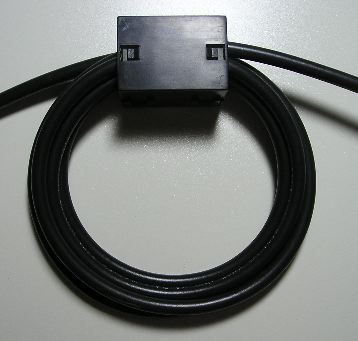
These ferrites listed hear are no way large enough to wind several loops of RG213 size coax. These ones simply snap on the RG213 size coax which does hardly anything for creating a choke much less being much effective for common mode rejection unless you use 50 snap on ferrite beads on it.
A choke should look like this using smaller RG8X size coax. DX engineering sells 3/4 inch ferrite beads like the one pictured here which can take about 7 turns of coax.
The general idea of using a choke is to keep common mode currents from entering your shack in the first place. Therefore, as I posted earlier, you need to place a choke at the antenna feed-point. If you are using RG213 size coax, then as I posted previously you need a barrel connector and at least 9 ft of RG8X coax to coil up with a ferrite bead to connect between your antenna and larger coax.
Here is a paste from K0BG webpage that gives some technical detail even though it is a Mobile HF information website, the theory still applies.
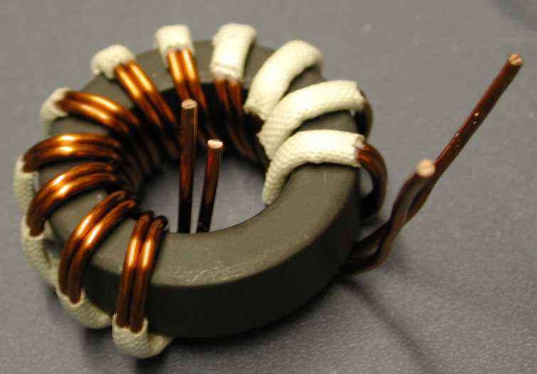
After proper mounting, the next solution to control common mode current is to install a choke. In this case, the choke is nothing more than a ferrite split bead, with a few turns of coaxial cable threaded through it. In fact, you can use the same type of split bead that you use for the motor control leads. That is, mix 31, and preferably the 3/4 ID units. They can be purchased from DX Engineering (et. al.) for about $30 per bag of five including shipping. These beads will allow 6 to 7 turns of RG58 or RG8X (as shown in photo). Note that the coax is not tightly wound around the choke. In this case, the diameter is about 3 inches. Any tighter, and the core could migrate and cause a short.
The resulting choke exhibits an impedance of about 2.2 kΩ at 10 MHz, which is typically enough for 80 through 10 operation. However, if you're really careful, you can wind 7 turns of RG8X through a 3/4 inch ID bead. The resulting choke impedance would be about 2.7kΩ at 10 MHz, and may even prove adequate for 160 meter operation (≈1 kΩ at 1.8 MHz). If you need more than that (trunk lip mounting?), simply snap on a second bead which will (almost) double the impedance. It should be noted that the impedance of the above chokes are primarily resistive at 10 MHz, an important design parameter.
The choke should be installed as close to the base of the antenna as possible. The last place to install them is inside the vehicle. After all, we want to keep the RF on the outside, not the inside of the vehicle. Fact is, the inside of a vehicle is almost as RF noisy as the engine compartment. Knowing this should be prima materia about where to mount a common mode choke.
How much choking impedance you'll need is not a cut and dried scenario, but there are factors which need to be considered. Those nifty appearing, clamp type mounts seemingly are the rage. However, the fact remains they add to the level of common mode current. Remember, the further away from the ground plane the base of the antenna is mounted, the greater the common mode currents.
It should be noted that antennas mounted through sheet metal via ballmounts will exhibit a bit less common mode than a similar height antenna fed outside the vehicle. Nonetheless, a proper choke is still required to minimize both egress and ingress RFI.
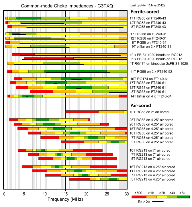
Here is an important fact to keep in mind: A multi turn choke will have much better common mode suppression than an equivalent one made up of a series of single turn ones. Further, in order to duplicate the total reactance of the choke shown above (7 turns, 3/4 inch ID, mix 31 split bead, ≈2.2 kΩ @ 10Mhz) on RG213, would require 49 similar split beads. That's about $275 worth, instead of just $6! However, there is another factor which needs to be considered. Impedance wise, it is imperative that the resistive value (in ohms) be larger than the inductive value (in ohms) if the choke in question is to be effective over a given bandwidth. Referring to the common mode impedance chart on Steve Hunt, G3TXQ, web site, the black line in the chart represents the resistive value of the represented chokes. In order to achieve this, the SRF (self-resonance frequency) needs to be within the frequency band of interest. To better understand this premise, read the verbiage accompanying the chart. Here's a hint: Compare the length and position of the black line in the chart with respect to the number of turns comprising the chart. Remember too, coax wrapped around a ferrite core is a tuned circuit.


")