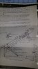
• You can now help support WorldwideDX when you shop on Amazon at no additional cost to you! Simply follow this Shop on Amazon link first and a portion of any purchase is sent to WorldwideDX to help with site costs.

My Lightning 6 Quad antenna

Dennis I added four ? marks for areas the I would like to know the dimensions for.

I have a small 3.875" adjustment to add to my model based on the numbers you just posted, but when I add my current wires all together I get 137.207 inches. If I add the 3.875" adjustment I get 141" inches and that is right on with your numbers...if the wire length from the last insulator to the radiator is close to 70.8" inches.

What was the overall length of the wire including the brass rod you used
considering the 147.5" inches you posted earlier? Did you have to use all of the 147.5" inches?


I also added some of the penciled in dimensions you posted earlier to your image below just for your clarification to see if I got them right. That said, I assume the plastic wire insulators are approximately 2" x 2" inches, right?

If you see any thing that is not right let me know.

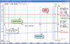
My model still does not match regardless of where I put the tap point on the 18" inch brass rod. If you're getting a workable match, where on the brass rod did you locate the tap for the horizontal polarity?

I probably have a problem with voltage fed models that I don't understand. I can select either current or voltage, but maybe I'm missing something else. The match on my model does improve the reactive match portion at the feed point some, but it is still showing a boat load of capacitance. The model acts like I have not added the inductor to the model.

I hope you can give us some good images of your analyzer when you get time. Are you using a flash on your camera?

I can see you're working hard. Thanks!
I found a mistake I made.
The flexible part of the tuner wire that is 12 gauge is 123-3/4" long + 18" brass = 141-3/4". I hope this helps with the model.
Hopefully the attached drawing will help clarify the other measurements. The hole spacing in the plastic is 1-3/8" and they are about 2" square but I forgot to measure them tonight.

I adjusted the horizontal and vertical feed points but it doesn't seem to make a lot of difference. It maybe brought the horizontal down about 50 khz or so. It is resonant at about 28.592 instead of 28.400. I think they usually go up in resonance when up in the air, I hope not.
I have some better photos here.
What do you think? Is it safe to put up?
 

Attachments

  • L4FeederMarkedUpNewMeasurments.jpg
    L4FeederMarkedUpNewMeasurments.jpg
    1.8 MB · Views: 274
  • L4VerticalFeedpoint.jpg
    L4VerticalFeedpoint.jpg
    1.1 MB · Views: 236
  • Horizontal Feedpoint.jpg
    Horizontal Feedpoint.jpg
    1.1 MB · Views: 261
  • SWRSweepHorizontalAfterAdjustment.jpg
    SWRSweepHorizontalAfterAdjustment.jpg
    2.2 MB · Views: 264
Do you think the baluns may be increasing the bandwidth, I think I have seen before when adding a balun.

Dennis, I don't know the effects you might experience using the balun. What does the manufacture say about effects vs. losses if any? DB is the man you might want to talk to.

I would NOT have added the baluns until I got the match like I wanted it first. You can still check it out before you raise it up and see if the BW is closer to the 0.50 MHz like LA's told you to expect. Then if you don't see any difference you can decide how you want to proceed. Consider that LA might have measured the BW at the feed point, like I do with my models. So, if you read it at the end of a long working feed line...then you could see a difference too.

Typically a little more bandwidth can be desirable, but it might also suggest an increase in losses. I have no idea how much however.

If the manufacture publishes the bandwidth and my model shows a good match, I can use the <2.00:1 SWR bandwidth to help me verify the model.

I adjusted the horizontal and vertical feed points but it doesn't seem to make a lot of difference.

I see the tap point on your horizontal is very close to the insulator at the starting end of the brass rod where it bends. My horizontal tap point is 2.5" - 3" inches from the start of the brass rod and the first insulator a little beyond where I see your tap. I have not added the vertical polarity to the model as yet.

Your vertical polarity looks to be located near the far end of the brass rod where it attaches to the wire. I will have to study the effect of changes to the tap point on the brass rod, but I would expect a lot of change to the resistance as I move the tap about. Maybe I'll see a little change to the reactance, but I doubt the antenna will go down in frequency to 28.400 MHz much less 27 MHz like you're seeing.

So, I have to consider that I still have an issue in this model, but it looks to work right now.

My horizontal model below is using your latest dimensions and is resonant at 29.1 MHz. It shows a near perfect match with R=53.67 ohms, X=0.0662 ohms, SWR = 1.073, with a <2.00:1 SWR bandwidth from 29.850 - 28.7 = 1.15 MHz.

What do you think? Is it safe to put up?

You told me early on you did not want to be going up and down on the tower. I would spend a bit more time with it first, but that is just me looking back at all the mistakes I've made getting into a big hurry. My Daddy use to drum into all my brothers and sisters heads, saying "...if you don't have time to do it right the first time, when will you ever find time to do it over."

I would double check that everything is tight and not too tight, and guy the mast like you said. If you like the match...then put it up on a pushup if you can, maybe 18' to 30' feet and see how it compares to the Imax or if it changes in any way. This way you can see what happens to the match and CMC's, etc..

Then go up on the tower.

Below is my new L4+ horizontal model using your dimensions, but it is not resonant at 28.400 MHz. It is resonant at 29.1 MHz and shows a very good match with the tap point about 2.5" - 3" inches out from the first insulator on the brass rod...like LA's suggested in the manual as a starting point for the tap.

Now is the time to slow down and make sure.
 

Attachments

  • L4+ model at 29.1 mhz.pdf
    878.1 KB · Views: 256
Last edited:
After you got the correct dimensions from me you really got it figured out!
There is a lot to understand here so I will reread and comment later. Just 2 quick questions.
1. Moving the feed connection closer to the end of the rod should bring the resonate frequency down?
2. Is the plot in freespace?
Great job with the model.
I'm going to try some of your suggestions today if I have time.
 
After you got the correct dimensions from me you really got it figured out!

I thought that too at first and then I decided to do an SWR scan over a range like you did and see if it made a difference. I have not gone back to my earlier model to do the same. It too might show the same problem...the frequency was wrong and the thing is very narrow banded.

I think I may have mentioned that IMO the Quad is very sensitive to the match...even though I seem to recall someone saying the opposite...maybe even in this thread.

I just got this model to working this morning after looking at how you had your tap points and I have not taken the time to try and diagnose problems even if I can.

1. Moving the feed connection closer to the end of the rod should bring the resonate frequency down?

That may be Dennis, but I was moving the tap on a dipole once and I seem to recall the reactance went up and then went down as I moved toward the open end of the wire. It confused me. I'm not sure a matcher is linear.

2. Is the plot in freespace?

No, I have not done a free space model yet and I may find I should have...if the Average Gain results are not good.

I'm going to try some of your suggestions today if I have time.

I would take the balun off and check the bandwidth to see if it did make the antenna more broad banded. And then check the specs for the balun thru-put or test it yourself and see if it shows any loss.

Note: when the 28.4 model was set to 29.1 MHz the currents on the mast were reduced considerably. You might recall that I originally posted a Quad demonstrating how much current might be expected on a quad beam. To me this might suggest common mode currents might not be a problem around resonance and if the beam is narrow banded you may never experience the effects. This is just and opinion however and has to be evaluated in each installation to be sure.
 
Last edited:
Dennis, I just change the frequency on my old original 28.4 MHz model that was not working right with a very bad match...and the change to 29.1 MHz fixed the model noted below in the PDF file.
 

Attachments

  • SWR bandwidth curve at 28.4 vs. 29.1.pdf
    882.9 KB · Views: 245
Dennis, I just change the frequency on my old original 28.4 MHz model that was not working right with a very bad match...and the change to 29.1 MHz fixed the model noted below in the PDF file.
Looks like LA may be off and maybe nobody looked close enough to notice before.
I'm headed out to try direct feed no balun just short stub and 1/2wl coax.
Attached is the balun specs. I don't really understand RL but it think it looks very good?
 

Attachments

  • 1-1 5kw Scan.jpg
    1-1 5kw Scan.jpg
    193.6 KB · Views: 201
I do think if a beam has a high magnitude of CMC's it can dramatically ill-effect the pattern.
 
Last edited:
I do think if a beam has a high magnitude of CMC's it can dramatically ill-effect the pattern.
Yes I think I saw a 2db change on one of your plots, I am willing to give up a little RL for a better pattern.
I have some data I have collected today.
I don't see a lot of change moving the feed point. I moved a couple of inches either side of 3.5" from the end of the rod and 3.5" seemed best overall. Moving toward the end of the rod did decrease the resonate frequency slightly but usuall the minimum swr went up a bit. I saw more chang just from moving the beam around so I left it at 3.5" for testing with and without the balun.
I have SWR and RL sweeps and also the SWR I measured from the shack with RF.
What do you think?
L4+ 7 ft off ground Horizontal SWR measured LP-100A
BW 2:1 ~ 1.4 Mhz
28.075 - 2.01
28.375 - 1.67
28.675 – 1.38
28.975 – 1.25
29.275 – 1.65
29.475 - 2.01
29.575 – 2.26
 

Attachments

  • L4+7TfOffGndHorizontalReturnLossWithAndWithoutBalun.JPG
    L4+7TfOffGndHorizontalReturnLossWithAndWithoutBalun.JPG
    270.1 KB · Views: 220
  • L4+7TfOffGndHorizontalSWRWithAndWithoutBalun.JPG
    L4+7TfOffGndHorizontalSWRWithAndWithoutBalun.JPG
    286.1 KB · Views: 276
I've been intending to lower my model to 7' feet above ground too, but kept forgetting. That might be making some difference in frequency as well.

Sorry to put you to all the added work. This has been going pretty fast for this old brain to keep up with.
 
I'm glad you encouraged me to look closer.
I ended up with the Horz feed at 3.5" from the end of the rod and the vert feed at the very start of the brass rod. Then I found a way to raise it 3 feet which is 10 feet to the boom and the vertical is starting to look a lot more as you would expect.
Considering the effects of cmc I think I will stay with the baluns and feel more confident that the pattern is as it should be. I do have some measurable cmc with the meter I recently built, it is not calibrated but relative to my iMax it is showing 22 microamps less cmc. The iMax has no balun. Anyway all that is testing for another day.
It would be interesting to see a model at 10 feet to the boom when you have time.
Yes, lots of data here, I need to reread everything a couple of times and go from there.
 

Attachments

  • L47Ft10FtHorzWithBalunCompareSWR.JPG
    L47Ft10FtHorzWithBalunCompareSWR.JPG
    295.9 KB · Views: 200
  • L47Ft10FtHVertWithBalunCompareSWR.JPG
    L47Ft10FtHVertWithBalunCompareSWR.JPG
    299.1 KB · Views: 196
Dennis, I have finished my model with both vertical and horizontal matchers at 36' feet. I still have to tweak the vertical side a little bit to get it squarely in the middle of the boom, but it is close.

I still have not lowered my model yet. I've been working with very small details getting the vertical side modeled and it is not easy with the horizontal matcher so close by and often times in the way of seeing what I'm doing.

The model also shows the best match with the tap point at the 14th segment...the last segment for the brass rod where the wire is connected. It is just like you reported.

I was amazed to find that the vertical polarity does the same thing as you've reported except the frequency only drops down to 28.7 MHz...instead your results at 27.4 MHz. It ended up with a 1 MHz bandwidth at the feed point instead of the 0.50 that LA suggested to you.

I have a little more checking to do and then I will post the models. I hope my posting all these models does not just confuse the issues. This has been a work in progress and it does get confusing at times, so bear with me.
 
Marconi, you are really getting that figured out. This has been kind of a rambling thread but if someone follows from beginning to end I think they will better understand the Lightning Antennas dual polarity quads. And when you have the completed model that will be great!
After raising to 10' at the boom I was able to point the beam roughly at the local truck stop which is 8 miles from me as the crow flies. They have been talking up a storm, some of which would make a sailor blush but is perfect for testing the iMax at 57' to feed point vs L4+ at 10' to boom. The radio is an Apache Labs Anan 100D and has a very accurate receive meter which I can read out in dBm.
The noise floor is 8db less on the L4+ vs the iMax and average the received signal from the beam heading is an honest 5db stronger on the L4+. The comparison is rather amazing!
Now there is a couple of things working against the iMax.
1. It does not have a balun or radials and has quite a bit of cmc which may be contributing to the noise floor.
2. The iMax is at 57' to the feed point on another tower. It is 60' from my 88' tower which is next to where the quad is. The 88' tower is almost aligned with the beam heading and truck stop so the iMax is kind of behind it. Could be an influence.
I'm giving a lot of details because sometimes details matter.

I'm going to try to email the video to you Marconi if it isn't too big. Or maybe I can post it to my youtube but the language is pretty bad.

When you get your model finalized I have a couple of requests. Maybe one with the boom 110' AGL and also one checking the influence of the iMax above it at 119' AGL. :)
 
The model also shows the best match with the tap point at the 14th segment...the last segment for the brass rod where the wire is connected. It is just like you reported.

I was amazed to find that the vertical polarity does the same thing as you've reported except the frequency only drops down to 28.7 MHz...instead your results at 27.4 MHz. It ended up with a 1 MHz bandwidth at the feed point instead of the 0.50 that LA suggested to you.
I was impressed as well when the 3.5" feed point attachment was the sweet spot for the horizontal side.
I think LA quoted me the 1.5 SWR BW.
 

dxChat
Help Users
  • No one is chatting at the moment.
  • @ Wildcat27:
    Hello I have a old school 2950 receives great on all modes and transmits great on AM but no transmit on SSB. Does anyone have any idea?
  • @ ButtFuzz:
    Good evening from Sunny Salem! What’s shaking?