• You can now help support WorldwideDX when you shop on Amazon at no additional cost to you! Simply follow this Shop on Amazon link first and a portion of any purchase is sent to WorldwideDX to help with site costs.

Cobra 29 LTD Classic

I'm not asking you to check D8...

I want to know if D8's place in line, has a short. Either on the Unbanded Side, or the Banded Side or BOTH...a dead short from the LINE D8 is on, to Ground - if it's a short dead short, you have a problem...

IF your posting is correct, you have a short AFTER D8 from the Mod Transformer, and PAST it to the MOSFET mods you did.

So you have to fix or determine how to fix, this short. Again, you isnalled a mod to replace the transistor with an MOSFET part.

Look a post or two above...
upload_2021-1-28_8-25-20.png

You have to unsolder the legs of the MOSFET and the Driver from the board, removing them from the output side of D8 circuit and test this again...Using D8's Band and Unbanded sides to check again for shorts to Ground.

IF you still have shorts to ground you have to isolate - look follow that Trace from D8 to the parts still soldered in and throughout the line looking for shorts or bad soldering

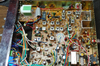
Use the photo clip above to make sure your not having your parts shorting out your system.
 
  • Like
Reactions: tecnicoloco
Okay, I had removed D8 due to letting the smoke out when powering up the rig.
I have also removed the Mosfet all together.
I have no continuity on the Cathode (-) to transformer ground. When checking the Anode (+) to transformer ground I get a quick signal of continuity but as quickly as I see it on the meter, it quickly goes away. Maybe this burst of signals comes from down stream being slightly charged from the meter when checking checking either side of the D8 with the meter, D8's diode is removed.

So with mosfet removed there is no continuity on either side of D8. I wonder if I should reinsert a new D8 before reinstalling a new mosfet to see if any smoke will reappear?
 
Last edited:
Actually I am getting a continuity reading from the Anode side of D8. I stepped the ohm meter up to Kilomhs and it read .833. So I stand corrected, sorry.
 
Ok, that's better, now lets' look into why...

How old is that radio? Any history behind it can help us in knowing what you're dealing with...

Ok, D8 to the Driver and Final - two parts share the same line - now it looks like the Driver may be damaged too. You'll need to verify.

Ok, to help - disconnecting the Final - leaves the Driver still in place, and you're now reading 0.833 in the 2K (or 1K) setting - which means you have an 800 ohm load across the lime somewhere. It may be VR4's(or VR5 per version) influence - so adjust that pot that is circled in the pic below, that has a lead soldered to the line that goes to the LEFT in the photo, this line is from the Mod Transformer on the right side PAST D8.

If it changes your reading then relax, it's the MOD pot placing a load across the line - it's a sense adjustment to adjust MODULATION levels .

I've helped others doing this so you may need to read a thread about Cobra 29 elsewhere I've worked with...It has hints to helps us in this post...

Read this thread...
https://www.worldwidedx.com/threads/cobra-29-ltd-classic-not-transmit.228821/page-4#post-624987

And this one...

https://www.worldwidedx.com/threads/cobra-29-ltd-classic-no-rx-tx-help.253718/page-2#post-716011

And this one...

https://www.worldwidedx.com/threads/cobra-29-ltd.257240/

Now, you'll see a lot of other people on this site also put their 2¢ (cents) in a LOT of effort to help us solve problems with radios - so I CANNOT take ANY credit for others whom are willing to share their knowledge with others that use this forum.

When you thank me - you really should thank the Forum for letting be be here in the first place - they have to put up with me - even on slow news days...

Ok, to put this back on the rails... remember too, that some radios like the 25...are using Mod transformer, and Limiters, and D8's but called D10's for the same reasons - only the package is smaller or changed - to protect the innocent...

Because they are similar, only the part locations and numbers are changed - but they are essentially the same type of process...Audio thru a big cap, into a Transformer tapped with Battery Voltage then passed thru a Diode then onto the Driver and Final...

Ok, since 2078 is not everyone's forte for fun...

Another one to help with that MOSFET mess you're dealing with...

https://www.worldwidedx.com/threads...-and-the-correction.157713/page-2#post-723522


Ok, onto the Patient...Pass the Rusty Saw please...


upload_2021-1-28_17-43-42.png

It's not the best photo but hope this helps get you started.

To help you further, unsolder that VR4 from the board, to remove it from the line. Save it for later to be reinstalled after we fix this mess...

Locate The Driver and Final section - it has a cap right by JP29 - JP29 feeds the Driver from the same line that L15 - feed the Final from. This line is the one I'm concerned about - for if the cap , by JP29 - is bad, replace it - this could be your entire problem...old caps...have been known to place a load on the Audio BIAS (Modulation) line and pop open D8 like a fuse

So if you remove VR4 and the Ohmmeter still shows that 0.833 - then unsolder that Driver Middle leg from the board , and check again.
upload_2021-1-28_18-40-22.png

In doing this, you are removing the Transistor from the main feeder that has the strange problem of blowing D8 or the fuses on the radio.

If once these transistors are out of circuit to that line, yet is still shows a short, then you'll have to locate the parts still connected on the line that are causing this. Not many are left connected - so it should be an easy fix

Reconnect that Middle Leg, (called the COLLECTOR) or in a MOSFET (DRAIN) on one, then recheck that ohmic - if it returns - that part is suspect, remove it and replace or reseat it to make sure it's not sorting out to any part of the mounting flange it's mounted to.

Same applies to the FINAL - again recheck the Ohmic results.

I'll stop here, you have a lot of catching up in reading to do...
 

Attachments

  • Cobra29XLRComponentside.png
    Cobra29XLRComponentside.png
    18.8 MB · Views: 22
Last edited:
  • Like
Reactions: Shadetree Mechanic
Hello and thank you Andy for the links.

The sticker on the back shows Feb 07, so I guess 2007.
Only history I can mention is it had an echo board installed that I had taken out.
Also it has a piggy back potentiometer for the swr cal and a talk back volume control that is still installed.

Before I can move forward, I need to know if I am thinking correctly here.

I may be thinking in the opposite direction of the circuit.

With the D8 removed I am not getting any continuity from the Cathode side to the ground of the modulation transformer / foil side . Please see "Pic" within the white circle.

However within the yellow circle in the "Pic" which I am trying to show the Anode side of D8 and the ground of the modulation transformer, I am seeing the 833 ohms.

So if I am thinking correctly "VR 4" is in the other direction, meaning it will not have any affect on the 833 ohms that I am seeing on the other side of D8 the Anode side. (D8 is removed)

Please forgive me if indeed I am thinking backwards here and please correct me.
Also just a reminder the final is removed as well.

Again thank you Andy.

upload_2021-1-31_9-18-4.jpeg
 
Ok! Thanks for helping explain your readings...

upload_2021-1-31_17-8-29.png

Sigh, ok, to help, doesn't look like anything is truly wrong on the D8's Audio Transformer side. - You are ok, that 833 ohms - if you look on the Graphic I sent back with your details - there are two resistors that act as a Divider to help set MIDPOINT for the Mod Limiter Circuit that uses VR 4 - once modulation gets into the line that D8 feeds the Driver and Final with - the DETECTED power across C73 - starts to DROP - the Limiter circuit senses this and begins to act. It's why I asked - to help you find this problem - you may need to remove C73, R73 and R72 - this will clear up that 833 ohm reading - it should go up HIGHER in ohmic value - keep them out of the circuit until we get D8 to quit blowing up on us. - Right now, if we left them in, it can goof up the readings we want to see.

Ok, for the other confusion, to put in 0 ohms, means you have a short, dead short, if that is typed in error - you're ok, just a typo, I use 1.000 as above to show the Ohmmeter is waiting for input - the leads show infinite. IF that is what you get - you're good, let's proceed.

then...
upload_2021-1-31_17-19-50.png

AND

upload_2021-1-31_17-26-24.png
So don't forget to UNSOLDER the Driver legs too...​

Once the Cage is out of the box, you can then work on realigning the transistors so they don't cause any shorts to the side of the cage.

The Cage not only dissipates the heat, it also forms a RF shield and ground using rivets and tabs soldered to the main PCB and parts that isolate DC, but keep RF flowing into and out of Ground at that cage.

You can then properly seat and check for shorts to the Cage - for if there are any, be sure to use alcohol and a wipe to remove any chips, shavings, dirt and debris from the backsides of the transistors and use FRESH white heat sink paste (no not the grey it is also CONDUCTIVE to DC too) Again clean the Hardware of goo and burrs dirt and shavings - reassemble the hardware in proper order as shown earlier and recheck for shorts.
  • To reduce errors in reassembly - Use your photos and mine together to help put this back properly without having further damages or bad soldering in reassembly from interfering with your work as you put this back together.
  • Doing this in steps will make it simpler
    • Clean, remove excess solder from tabs
    • prefit cage and check it's alignment holes for it's mounting screws
    • same for transistor legs so they fit thru the slots so they can be resoldered
    • locate any parts on the components side and make sure they get soldered to their proper places on the Cage.
    • Note the cage to SIDE PANEL bolt, it's Nylon and uses an insulating washer - this prevents the cage from shorting to CHASSIS in error.
    • Begin reassembly by;
      • Align tabs and transistor legs and place the cage towards it in-seated position and carefully align tabs flanges, slots and legs to their locations they feed thru on the main PCB.
      • Press cage gently into the main PCB and align IT'S main Lug near centerline of the board ahead of rear panel.
      • Align and install side-panel spacing insulator washer and Nylon bolt finger tight...
      • using a side to side and twisting motion - align mounting flanges to bolt holes in main PCB
      • install the installing Mounting bolts thru their tooth washers into main PCB - do not tighten them at this time.
      • review tension and alignment and reflow solder on the main Ground Mounting Tab as needed to help seat the board
      • - at this time tighten the main PCB to Cage Flanges bolts observing the alignment of the transistor legs fed thru their slots
      • verify the Cage shorts only to Main PCB Ground not to side panel or chassis ground points for main PCB Board mounting.
      • Reflow solder to transistors - check for shorts and they are not touching CAGE - verify all component LEGS that they are standoff from and not pinched by or otherwise shorting to cage.
Once the Cage is positively clear of shorting to tab or other issues - realign the tabs to fit the holes, legs to fit the slots and start putting this back together. See above...

  • Remember!
Reinstall MOD Limiter parts C73, R72 and R73 once you've verified that D8 is not shorting out to the CAGE or any parts it is NOT supposed to be connected to.

Solder in D8 - again check for shorts - finding none, do up a test keyup to make sure she shows wattage - else you may have issues with the MOSFET conversion and you'll have to go back to Bipolar 2078 to make this stable and work again - once that is complete, then look into what went wrong in the MOSFET conversion the first time and let's see if we can make it work this time.
 
Last edited:
Andy, you have the Patience of Job, seriously.
I feel really bad because I should had Not said " 0 " ohms. I should had said there is NO Continuity from the ground of the Mod tranny to the Cathode side with diode removed at D8. Meaning it is an open circuit.
 
We still have to determine if the hardware is causing the short, the part were fixing or if the Cage itself is touching a part it's not supposed to.

I have gotten radios in for repair that at one time of another had the Cage disassembled and put back incorrect, in several different ways - causing parts the Cage weaves thru - to strike or lay pinched by - the Cage that when reassembled, shorted it out and took a lot of parts, including the Mod Transformer - with it.

You just have to put the parts in and tighten it down so we don't re-create that condition.

Let's proceed!
 
  • Like
Reactions: tecnicoloco
Okay thanks Andy. Well I would like to mention when I received it, I had about 1.5 watts to the watt meter before starting this original posting.

As mentioned it had the RFX75 installed. After opening the rig up, I had discovered there was a fuse holder inside the rig and this fuse holder went to the RFX75.

When I placed a heavy fuse in the holder of the RFX75 that is when it took out the D8. So it is my belief from what I have experienced, it has something to do with the results of the RFX75.

After doing the mosfet transplant I found out it would still take out D8, realizing there is still a short. One thing that I discovered that I did not have an insulator sleeve around the bolt that that keeps the mosfet in place which could be the cause as well.

After de-installing the mosfet, I have not yet try to place a new diode in D8 to see if this would short again. Also I have not yet removed the driver transistor from the circuit.

I don't mean to derail anything that you are helping me with but I think I have not been to clear with my communications to allow clarification for your wealth of knowledge to lead in a possible fix or at lease to move in that direction.

After rereading and posting I have realized that I had not totally post exactly what I have or have not done, of course not intentionally!

I hope this makes more sense now.

Oh and another thought, when I turn the modulation POT, I do not see any results on the ohm meter.
 
Okay right after posting above I decide to install a new Diode in D8. Also I think I failed to mention I had replace C123 in the beginning. Well believe it or not, D8 did not melt!

It seems to be holding its own.

So it may be due not to have that sleeve on the bolt of the Mosfet when it was installed.

Should I move forward and try to install the mosfet transplant again?

Of course I need to find a sleeve for that bolt which I do not have on hand, but I may
be able to take one from another junker.

But I will wait to hear from you Andy.

Thank you.
 
Ok, now you're moving ahead!

You will need a mounting kit for that TO-220 style MOSFET part, you can't avoid this - it has to be an insulator washer in there...
upload_2021-2-1_18-12-59.png

Don't worry - don't sweat the small stuff, the effort I'm putting in this thread is for LEGACY purposes.

You don't see someone taking apart a radio to the point of where the CAGE that mounts the Driver and Final is even discussed. In some efforts of doing upgrades, this removal and reinstall of that assembly in a necessity to make the transition or conversion successful. I have not seen too many discussions of the physical aspects of this effort even mentioned - seems that many presume that others know how and won't bore others with the details.

  • I haven't seen too many posts about removing a key piece of support, and when you're a Tech - it's usually easier to take the parts off when it's cage is free in your hands.

This method from Cobra and Uniden - that Cage-style of install, works well. JMO to me it's the easier work - for working on the side panel and rear panel mountings of the heavier Galaxy, 148's Grants and Midland Realistic amongst the other brands - the slinging or having to simply put the radio into a cradle to hold it so you have access to the tops and bottoms of where the device goes, many Techs have done up test bench "jigs" to handle the standard sizes and use cloth rags onto formed vinyl gel pads to keep the scratches to a minimum.

  • For some they don't have a "Bench", more like a platform table that allows 360 degree access to every spot on the radio within simple reach.

This removal is allowing you the Flexibility to remove and install the parts back onto the cage and then once done, the hard part is simply aligning and reseating the Cage into correct spot so parts aren't crushed or otherwise left to short against the sides. The slots and holes are pretty much a gimme' - the alignment effort and if needed - rebending of it's angles to keep the Cage and the parts on it from shorting together once installed and soldered - that's the hard part.

So as you (or this applies to anyone) work thru, I presume people have a knack, or way or some methodology to take the parts laying on the bench and putting them in there to rebuild, replace or repair a key section of the radio.

  • I've beaten myself up many times for not realizing that there are other ways to do things and sometimes even the efforts I use are not the most precise nor are they the best approach to fixing. So as I help you, your feedback - helps me do my job better for the next time.

So since you have suffered at the bane of the MOSFET conversion - the job is easier if you remove the cage to help you obtain access, remove, clean, mount, align, reseat and tighten the parts on it - and then you also have the ability to inspect and TEST the cage for proper isolation and insulation from and that they don't short to each other.

The install of the parts on the cage, to verify the parts on it, are correctly mounted, and when installed, you just resolder and replace and tighten the screws. This step I thought everyone did, doesn't always mean that everyone does it this way.

So let me know how that MOSFET conversion goes. That insulation washer - best to take it from another donor, but if you have a parts store nearby - they may have those TO-220 hardware kits and the Heat Sink goo - sure it may cost some $$$ but if it works right, the cost is worth the effort because you didn't lose the part - or have it take out the parts it supports from a bad install on power up.

The Insulator washer, and that screw being the same threaded seating that the Cage uses - this limits your selection to just a few insulator spacer washers - so if a Donor is available - hate to suggest this, but yes, one will have to go to the other...

Sorry Frankie...
upload_2021-2-1_18-18-15.png
 
Last edited:
Hello,
Okay I have installed a new Mosfet once again on this rig.

The Red like tube looking thing is in the Pic is just Red Heat Shrink protecting the leads from shorting out.

Anyway as soon as I had turned the rig on, "D8" had started to smoke again.

Now prior to the Mosfet install, I could turn the rig on and "D8" would not let the smoke out!

In this order...
I removed C73 which is tied into VR4 and "D8" still was letting the smoke out.
I have also removed C42 which is tied to T2, (Transformer) again smoke from "D8".
Then removed L12 with no results.
Then removed the modified circuit to regulate the voltage for the Mosfet, with no results.
Finally I removed L15 (Choke) and "D8" stopped letting the smoke out.

Now as we know L15 (Choke) is tied into the "Drain" (Middle Leg) of the Mosfet.

Is it possible with the Modified Voltage Circuit that was created, could had shorted out the Mosfet causing a short that led into smoking "D8"?

The voltage regulator consist of a 470, 3.3K ohm resistor and a 1N4148 diode.
I have no real experience with Mosfet period!

Another thing JP36 (jumper) was reinstalled due to it being removed during the RFX75 installation. I was wondering if this would have something to do with this issue.
Again, No experience with Mosfet.

By the way I used a 1N4004 for "D8". I don't see why this would matter.

Thanks in advance!
and Happy Friday!

upload_2021-2-5_11-1-15.jpeg
 
Hmmm. Where to begin...

Yes, removing L15 demonstrated the MOSFET was turned on at the time - why? Check for the ON voltage at the Gate - because if you do like most people would do, and set "gate" to be 3.6 volts

Please don't...MOSFET's are not all built the same way...

I see you're trying to use something from earlier - and I think you're using this...
MOSFETCobra29.jpg

That is a screenshot, but it looks like you're trying to fabricate a part from EKL - using Discrete...

The 330 ohm kinda shows this...

So what values are you using and why?

Secondly...
upload_2021-2-5_11-39-0.png
You used way too much "goo"​

There are several types of this Goo - Heat Sink Compound - floating around and with it lathered on like, even the non-conductive type can provide D8 that shorting path thru this stuff because of too much applied to the back and Tab of that TO-220 then pressed in and bolted to a conductive surface - I'll leave that there...

Got to pull it (MOSFET) off, clean it up and use a little less
That goo, it can conduct - you may want to find a different brand of it. One that is truly the paste designed for TO-220.

Let's start over...

Cobra29TXStrip.png

Can't use R56 and L22 like that - this is an MOSFET not a Bipolar.

If you decide to go the Route of EKL conversion - be careful with the part selection...

The part values will change as the LOT numbers of each processing lot is done - their Gate Trigger ON voltage will change.

IRF520EKL2030conVUPDTDmod.png

In the above Graphic, R2 and R3 will change - so what you want to look at is the output power of the radio starting small (4 watts). Makes R2 LOWER in ohmic value and R3 even lower

These conversions - so these MOSFET will pass DC just as easily by LATCHING on and taking out D8 trying to suck power out of the radio to produce RF and DC - it's full spectrum ...
 
Last edited:
Hello Andy,

Yes I was trying to create the EKL as you had posted earlier in this discussion.
I used a 470 and a 3.3k along with the 1n4148 diode.
I used these values as I had seen in one of the Pics.

If I may ask, what resistors would you recommend for the EKL creation?
And in what configuration should they be arranged?

Could you send me a link to the Bi-Polar to Mosfet conversion?

As for the goo, these mosfet must be very sensitive compared to bi-polar.
But okay I will clean up the goo and put less on and perhaps find another type.

I would need a suggested valve of R1 and R2 though for the EKL creation.

I hope you are enjoying your Friday.
Thank you Andy.
 

dxChat
Help Users
  • No one is chatting at the moment.