And no S/RF indication?
You have RX Green light, but when you switch - Key the mic handset you get to TX - no red light correct?
You have RX Green light, but when you switch - Key the mic handset you get to TX - no red light correct?

And no S/RF indication?
You have RX Green light, but when you switch - Key the mic handset you get to TX - no red light correct?
Another step here to help, plug in the PA speaker in the EXT SP jack - and power up radio - any thunk or sounds from External?

No thud when I turn radio on with speaker plugged in to external speaker... when I work on a radio I pull the speaker cover I usually plug in external speaker
So if we can see about opening the PLL and see if we get LOCK...
Set Channel Selector to Channel 9 ...
Volume 50%
NB/ANL - Off
You just need the DVM to measure a Test Point - they are simple "standoffs" from the board you can put a regular Test lead (they'll let you know if it's special purpose) and this test is Voltage reading to see if the PLL can send a voltage to tune an oscillator circuit that uses a Varactor.
To Test,
Note what I asked you to set up...Some people say to use Channel 1 and 40 - yes, you can, but in light of the time this chassis was made, HELP and Channel 9 REACT was popular, so they really made more of an effort to allow the radio the best chance at powering up around the 27MHz frequency and most success towards Channel 9's Channel Frequency 27.065MHz - I just want you to be able to check for the PLL if it would even FIRE up to oscillate...
- you apply the Positive (+) lead to the Open Bare Lead that is folded over to expose your connection point.
- The NEGATIVE lead goes to a simple IF Can Case .
- or if you wish to use one a Bare Wire Strip soldered across the gap between two IF cans can work too. But that type of test jig is only necessary for long test duration problem requiring a known mounting location to help support the test equipment grounding needs.
Do you have any Ceramic tip tools? Non Ferrous, Non Metallic - RF transparent type of tuning tools around?
Because you'll need to remove the Wax plug on L22 and around the Test Point Standoff resistors to get a good clean contact as well as ability to tune the slug without breaking it.
In the steps above, they mention an Oscilloscope - unless you had to rework a tuning circuits' bad NPO caps or a leaky Resistor - you can really do this without one for it can add more confusion that you don't need to have thrown at you right now.
We will do this a little differently - we locate the Cans were going to tune - and if needed - take a close up pic of them using your smartphone to help you orient them and remember their initial settings when you started - its' a documentation process step you will find useful in having to go back in and adjust something - at least you'd have a clue as to where you started at. I'm referring to the slug, its' slot - how far down it is in the form - can provide clues as to their condition and if someone tampered with them - they stopped in this position. So as we work thru the and walk thru the tuning - the slugs will play an important role in the start along into the final adjustment stages.
See below this post, there are two attachments - look for the Cobra29 TP2 - and review what I mentioned above.
It may not hurt to use a marker to "score" along the flat of the slug for Alignment. You can also see I labeled the two mentioned in the PLL Alignment Section. The TP2? You can just keep the DVM on that "post" for this entire test.
Why?
If you seem to lose lock - at anytime from this step onward...
- - as you re-tune L22 - you'll see the DVM readings jump around - once they go steady, you have a lock, you may also hear a "hiss" or air-noise from the speaker - you have a receiver! TX? Don't push it yet....
- - Turn the Channel Selector slowly - you should hear the hiss - if the "hiss" disappears - then you've lost lock - take a moment and "tweak" L22 again to see if you can regain a Lock and the Hiss...
- Once you've got the Hiss again, try changing the Channel Selector to Channel 1 and Channel 40 bounce between the two several times using the Channel Selector clicking back and forth - to ensure the PLL and L22 can Lock on all the channels in between 1 and 40.
- Check your DVM reading on R88 and Change Channel to Channel 1 - note reading and Change to Channel 40 - this Reading should be 3.2 Volts - if not - Locate and Retune L19 until it's says so.
IT mat seem redundant to do the step twice - but no - you don't need to do it twice. I put it up there for one of the first things you may do is to try and adjust the other coils around it - this can change the LOADING the circuit the coil uses in under - which may affect the tuning and the PLL may lose lock
- Check R88 and DVM readings. When the PLL goes "out of Lock" it means it can't track the frequency the Oscillator uses. So the DVM readings are pretty much all over the place in high voltage readings of 6 volts or more or really really low voltage ones... That means it's out of lock and you have to "tweak L22" again to obtain and hold lock. To know you've got lock, is when that voltage stays steady at one set voltage.
- Set Cannel Selector to Channel 40 and Adjust L19 again for 3.2 volts.
Now things will get dangerous. For if you can hear the RX hiss, that also may mean you can TX too - time to put a Dummy load on the Back of that radio to protect the Finals from blowing out due to NOT having any antenna or load connected to accept the power the Finals will put out.
As you adjust, the cans for RX and TX are slightly different to each other - so the radio will shift with an offset to align the frequencies it generates to meet the channel - this may put it out of lock. So be ready to adjust L22 to improve it's output so you can obtain the signal and the PLL can hold a lock again.
I'll stop here...for now... see below for details...
") ... i better under stand the schematic... just to recap... i do have static now!!!! i also did replace the volume/squelch pot. because the volume control was ever so sightly bent... may have been droppped!!!???? then proceeded with your voltage checks/adjust at L22 and L19.... PLL locks now and i have Static...
... i better under stand the schematic... just to recap... i do have static now!!!! i also did replace the volume/squelch pot. because the volume control was ever so sightly bent... may have been droppped!!!???? then proceeded with your voltage checks/adjust at L22 and L19.... PLL locks now and i have Static...
Ok, will give it a break for now...
I don't think the radio is SEVERELY damaged, but if the radio has been dropped - we may have more of physical than electrical problem on our hands.
Ok, that may mean you'll have to pull a part or two - you up to it?
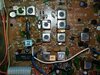
Wanted to give this to you too...
This is the Driver and Final section...although I do not think it is bad per-se. It is an area to check for cracks and broken joints. There is a big heat sink panel back there that is bolted to the board but not sure if it survived the jostle / faceplant from the previous owner.
Parts can shift, and boards can crack and solder joints can come undone. IF you're having problems more with garbled weak audio but you have noise - it may be from parts that got shifted...
The other aspects may be it need a good tune up but right now you seem to have a lot on your hands.
Look above and compare it to your board - should look pretty much the same...
Will talk later...