Thanks for the SM guys...
Here's the help you might need...
To help understand this, the SWR meter checks RF reflected compared to RF Power going out.
The old days, the SWR meter use "resistors" as part of a trim network for it's "balanced bridge" design - you simply read the difference across the bridge.
Todays? The SWR meter uses Capacitance to provide the "shunt" effect.
The more the shunt - less reflected power is "seen"
You change the amount of capacitance to change the amount of RF "sensed" by the meter system - larger capacitance means more RF power is carried across it.
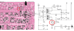
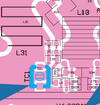
So to provide a way "out" TC1 a variable cap is used to provide a level of "shunt" to ground - so the SWR Reflected has to pass this cap to get to the meter. If the capacitor values are big, more RF is shunted AWAY from the meter - keeping the SWR showing LOW (or too low to be safe). To change or reverse this, you make the shunt capacitor small - Making TC1 smaller - less power is shunted away - so the SWR meter sees a larger REFLECTION value - and shutdown occurs if it is too great.
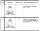
To make the SWR "correct" you install a 25Ω or 75Ω ohm load across the antenna connector and key up in full power mode - and set TC1 to show a 1:1.7 SWR.
Those menu options are "iffy" at best guess - use at your own risk.
When you locate TC 1 - you have two options...
One
View attachment 58171
Remove it - which is turning off the SWR feature
OR
Solder a short across "R238" resistor - forcing capacitor C39 and TC1 to shunt more REFLECTED RF power to ground - some will still go display at the meter
but the effectiveness will be a LOT less.


