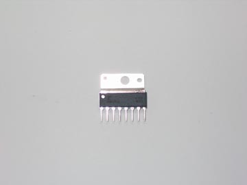
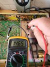
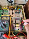
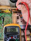
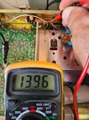
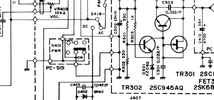
8. 6.48vplease measure all 8 DC voltages starting at pin 1 (rear) and list the voltages you get on each pin. they should not fluctuate.
LC
7. 6.50v
6. 6.49v
5. 5.09v
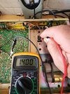
4. 7.50v
3. 5.06v
2. 5.09v
1. 6.45v
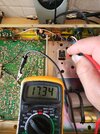
Voltage from fuse = 13.58v
Also, I now see one more led on the clock after 12:00 0<= this flashes?
Didn;t see that ever but it has been plugged in for a while.
Last edited: