Well, I'm up the creek on this. I got frustrated enough to put the scope back on the pins and it turns out that the rotary encoder is the cause of much of my trouble. If the knob gets rotated fast or pushed to one side, the ground reference for the data disappears and the data floats almost as if it were AC coupled. Didn't notice before because I was single-shot triggering. Even without data, if I move the knob back and forth, the clocks baseline voltage goes negative. I need to find a new encoder now.

You are using an out of date browser. It may not display this or other websites correctly.
You should upgrade or use an alternative browser.
You should upgrade or use an alternative browser.
-
You can now help support WorldwideDX when you shop on Amazon at no additional cost to you! Simply follow this Shop on Amazon link first and a portion of any purchase is sent to WorldwideDX to help with site costs.
-
A Winner has been chosen for the 2026 July 4th Retevis RA89R Giveaway! Click Here to see who won!
Bearcat 980SSB "PLL Porn"
- Thread starter brandon7861
- Start date
update: Thankfully, it was a bad solder joint. The encoder is good!!!!!! And I got that delay gone too, had to switch over to the actual SPI pins. Tracks as fast as you can spin it now. Back on track!

Got it working good, no errors or glitches. Now I need to know if I should add ch40 to ch1 roll-over detection for uppers and a knob gesture like Overkill did? Or do I just add code to support switches on the back? Or do I leave it as is with the programmable ch table?
Any suggestions would be appreciated. Thanks!
Any suggestions would be appreciated. Thanks!
If you have an extra GPIO pin you could set it up such that a high on that pin goes down a code path for switches on back while a low does the rollover/gesture.Got it working good, no errors or glitches. Now I need to know if I should add ch40 to ch1 roll-over detection for uppers and a knob gesture like Overkill did? Or do I just add code to support switches on the back? Or do I leave it as is with the programmable ch table?
Any suggestions would be appreciated. Thanks!
Programmable table is nice, but I can easily see people complaining because they can't understand why it's doing exactly what they told it to instead of what they want.
Never a fan of adding new holes in a chassis for accomodating new switches.Any suggestions would be appreciated. Thanks!
It's difficult to see, but can't you swap out a potmeter with a potmeter that has a switch? Or perhaps the current encoder does not have a push button function and you can replace it with one that has?
The rotary encoder currently goes into the menu when pressed. I don't like drilling holes either, but this already involves cutting three traces. i will try to figure out a button gesture system. Maybe that useless ch9/19 switch can be repurposed.
It would be cool to tie it to the color selection
It would be cool to tie it to the color selection
Last edited:
A "double press" on the rotary encoder like a double click with a mouse perhaps?The rotary encoder currently goes into the menu when pressed. I don't like drilling holes either, but this already involves cutting three traces. i will try to figure out a button gesture system. Maybe that useless ch9/19 switch can be repurposed.
It would be cool to tie it to the color selection
Agreed on a channel 9/19 switch to be completely useless and a good candidate for being repurposed.
My 2 cents. NO SWITCHES!Got it working good, no errors or glitches. Now I need to know if I should add ch40 to ch1 roll-over detection for uppers and a knob gesture like Overkill did? Or do I just add code to support switches on the back? Or do I leave it as is with the programmable ch table?
Any suggestions would be appreciated. Thanks!
In the case that you're in need for more switches.Agreed on a channel 9/19 switch to be completely useless and a good candidate for being repurposed.
If you can indeed repurpose that 9/19 switch then perhaps you can do something like short press is function X and long press is function Y?
I agree, no switches.
I currently have the SPI pins D10, D11 and D13 listening for the data (D12 tied up in SPI funcitons) and D2, D3 and D4 talking to the PLL. To get the speed I wanted, I had to use code that controls port D directly, so D0, D1, D5, D6 and D7 cannot be used reliably. That leaves D8, D9 and A0-A5 free. A6 and A7 are ADC only.
That leaves 10 inputs that can use to listen to different things for programming gestures. Just need to figure out how to do that. Been learning as I go here.
Here is how I am currently tapping into the three data lines. Once the code is done, I will remove the socket and put the nano back inside the radio. I don't want to bust the encoder plugging in the nano. I made a fingerboard and glued it down so I wasn't tugging on the fine wires going to the traces. I don't yet have UV resin, just UV mask, and that stuff is not strong so I superglued the fingerboard on..

This pin circled in red is the 5v source for the arduino. I made my fingerboard one finger too short.

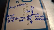
The only bad part is the need to invert the CS signal, so I currently have a NPN transistor inverting it before going to D10. Haven't figured out how to flip that in the code yet.
And here are the pinouts labeled. Dont forget that I have an external inverter flipping the signal from the radios CS (labeled D10 on the radio pic) before going into the arduino's D10 input pin.

And in case I never get back to it tomorrow, here is the code as it is now, with the channel tables. Instructions are commented out in the sketch.
Important... When you write to the arduino, you don't want radio power to it. If the radio is off, it pulls down the arduino voltage. If the radio is on, there is a small voltage difference. Just unplug the arduino power lead when programming via USB.
edit to add some notes in the arduino code
This pin circled in red is the 5v source for the arduino. I made my fingerboard one finger too short.
The only bad part is the need to invert the CS signal, so I currently have a NPN transistor inverting it before going to D10. Haven't figured out how to flip that in the code yet.
And here are the pinouts labeled. Dont forget that I have an external inverter flipping the signal from the radios CS (labeled D10 on the radio pic) before going into the arduino's D10 input pin.
And in case I never get back to it tomorrow, here is the code as it is now, with the channel tables. Instructions are commented out in the sketch.
Important... When you write to the arduino, you don't want radio power to it. If the radio is off, it pulls down the arduino voltage. If the radio is on, there is a small voltage difference. Just unplug the arduino power lead when programming via USB.
edit to add some notes in the arduino code
Attachments
Last edited:
I see a thing of beauty evolving before my tired eyes.Here is how I am currently tapping into the three data lines. Once the code is done, I will remove the socket and put the nano back inside the radio. I don't want to bust the encoder plugging in the nano. I made a fingerboard and glued it down so I wasn't tugging on the fine wires going to the traces. I don't yet have UV resin, just UV mask, and that stuff is not strong so I superglued the fingerboard on..
View attachment 75814
This pin circled in red is the 5v source for the arduino. I made my fingerboard one finger too short.
View attachment 75816
The only bad part is the need to invert the CS signal, so I currently have a NPN transistor inverting it before going to D10. Haven't figured out how to flip that in the code yet.
And here are the pinouts labeled. Dont forget that I have an external inverter flipping the signal from the radios CS (labeled D10 on the radio pic) before going into the arduino's D10 input pin.
View attachment 75822
And in case I never get back to it tomorrow, here is the code as it is now, with the channel tables. Instructions are commented out in the sketch.
Important... When you write to the arduino, you don't want radio power to it. If the radio is off, it pulls down the arduino voltage. If the radio is on, there is a small voltage difference. Just unplug the arduino power lead when programming via USB.
edit to add some notes in the arduino code
I've added channel tables A-H based on the table from Walcotts, I know some put the normal 40 in band D, this one puts it in E. If that is wrong, please let me know. I also added code to shift it down by 10k. If that should be up by 10k, let me know. Not sure that it would matter.
Still need to make the wraparound code and 10k gestures though
and getting too far away from 27MHz will require VCO coil turning, not sure if I should try to add in an auto-adjust.
Still need to make the wraparound code and 10k gestures though
and getting too far away from 27MHz will require VCO coil turning, not sure if I should try to add in an auto-adjust.
slowly getting there. I added code to detect the number of milliseconds between a fixed number of knob rotations and the direction it is turning, so I was thinking about doing 10k down and 5k up. The bands will casually roll over at the top and bottom of the dial. Still need to figure out an indicator. Would be cool if I could get a basic voice library and tie it to the audio amp.
Edit, there is, its called talkie! Cool!
Edit, there is, its called talkie! Cool!
Slowly?slowly getting there. I added code to detect the number of milliseconds between a fixed number of knob rotations and the direction it is turning, so I was thinking about doing 10k down and 5k up. The bands will casually roll over at the top and bottom of the dial. Still need to figure out an indicator. Would be cool if I could get a basic voice library and tie it to the audio amp.
Edit, there is, its called talkie! Cool!
")
dxChat
- No one is chatting at the moment.
