Turns out that my first chart was right after all. At work, when I tried reproducing that chart, I got dyslexic and typed in 15.36MHz instead of 13.56MHz and thats what shifted the chart up on me. I thought it was different for the reason I mentioned, but I had it right after all. It was todays chart that I messed up. Man I feel dumb now.

You are using an out of date browser. It may not display this or other websites correctly.
You should upgrade or use an alternative browser.
You should upgrade or use an alternative browser.
-
You can now help support WorldwideDX when you shop on Amazon at no additional cost to you! Simply follow this Shop on Amazon link first and a portion of any purchase is sent to WorldwideDX to help with site costs.
-
A Winner has been chosen for the 2026 July 4th Retevis RA89R Giveaway! Click Here to see who won!
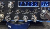
Galaxy dx99V2 off 4K on various channels
- Thread starter Chris Lawrence
- Start date

Ok, it's okay. So, back to this?
And bump, can I get some pll voltages on ch1?Okay, pin 3 of IC4 should be LOW on CH1 Band E, in order for IC4 pin 12 to go high. We need IC4 pin 12 to be high, so IC4 pin 3 AND pin 4 both being HI will make pin 12 LOW, giving an issue. It, pin 3, is staying HI, when it should be LOW, so either a channel switch or RA102 resistor is open and it is floating HI.
A 47K resistor from IC4 pin 3 to GND would determine if the RA102 is open for that line, or the channel switch is, in fact, faulty.

-IC4-IC5
1) 8-0
2) 7-0
3) 7-8
4) 0-7
5) 8-0
6) 0-7
7) 8-8
8) 0-0
9) 0-8
10) 8-8
11) 8-0
12) 0-0
13) 0-0
14) 8-8
15) 0-7
16) 8-8
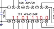
PLL: MC145106P
1) 8.2
2) 4
3) 4
4) 4
5) 4
6) 8.2
7) 2.9
8) 8.2
9) 7.6
10) 0
11) 0
12) 8.2
13) 8.2
14) 8.2
15) 0
16) 8.2
17)8.2
18) 0
These measurements don't match up.

PLL pins 14 and 12 differ from the readings from the adder.
PLL pin 14 connects to IC4 pin 13, the PLL voltage HI, but the adder voltage is LO. Same with PLL pin 12, connects to IC5 pin 11.
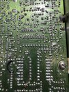
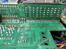
Can you provide a good pic of the back of the board, to see the traces from the PLL to the adders? This is a tricky repair over a keyboard. If it was right in front of me it would be fixed already.
The adder readings you gave add up right, with the final carry out going to pin 9 of the PLL. However, the PLL voltages you listed do not align with the adders. Either an error was made in reading, it happens, or you have blown/cut traces. That's where I'm at right now.
Looking at the scheme and the photo I posted, I believe I counted Pin1 as Pin18 then proceeded in a counter clockwise fashion. These ic chips don’t have a marking for a starting point.These measurements don't match up.
View attachment 75944
PLL pins 14 and 12 differ from the readings from the adder.
PLL pin 14 connects to IC4 pin 13, the PLL voltage HI, but the adder voltage is LO. Same with PLL pin 12, connects to IC5 pin 11.
Sorry about that. Please confirm I it correctly, or that I did it backwards. I can do them again or just read the numbers in reverse.
Attachments
Can you provide a good pic of the back of the board, to see the traces from the PLL to the adders? This is a tricky repair over a keyboard. If it was right in front of me it would be fixed already.
Attachments
No, pin 1 is right.Looking at the scheme and the photo I posted, I believe I counted Pin1 as Pin18 then proceeded in a counter clockwise fashion. These ic chips don’t have a marking for a starting point.
Sorry about that. Please confirm I it correctly, or that I did it backwards. I can do them again or just read the numbers in reverse.
Just remember it goes like this ..


Last edited:
SHOOT! Channel selector was on 36. These measurements don't match up.
View attachment 75944
PLL pins 14 and 12 differ from the readings from the adder.
PLL pin 14 connects to IC4 pin 13, the PLL voltage HI, but the adder voltage is LO. Same with PLL pin 12, connects to IC5 pin 11.
 brb
brb1. 8.2
2. 4
3. 4
4. 4
5. 4
6. 8.2
7. 2.5
8. 8.2
9. 8.2
10. 0
11. 0
12. 0
13. 8.2
14. 0
15. 0
16. 8.2
17. 8.2
18. 0
2. 4
3. 4
4. 4
5. 4
6. 8.2
7. 2.5
8. 8.2
9. 8.2
10. 0
11. 0
12. 0
13. 8.2
14. 0
15. 0
16. 8.2
17. 8.2
18. 0
Alright, according to the truth chart posted, that's channel 4 while on channel 1. If you have another channel switch, now would be the time to try it.
The adders are adding bits, the band switch is influencing the calculations, the pll is locked and outputting, I'm convinced a channel switch issue is causing this, or some channel switch fault between the channel switch and the adders.
The adders are adding bits, the band switch is influencing the calculations, the pll is locked and outputting, I'm convinced a channel switch issue is causing this, or some channel switch fault between the channel switch and the adders.
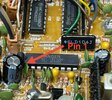
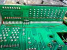
Check the 11m move the black wire mod. Solder blob looks a little too close to the pin next to it. Make sure the solder isn't connecting the second and third pin.
Oh man, I didn’t know you were still working on this. That’s why you were in the shop all day.
Ouch $$$ https://stores.goldeneagleradios.com/galaxy-dx99v2-channel-selector-with-frequency-counter-board/
Ouch $$$ https://stores.goldeneagleradios.com/galaxy-dx99v2-channel-selector-with-frequency-counter-board/
*Fixed! [Channel Board Replaced]
Replaced channel selector but it did not resolve the issue.
Bought a new channel selector board (complete) from Barkett @ $80/shipped. Problem fixed.
Man I hate doing these. Solder joints turned out clean, though. No traces pulled up.
Thanks for all the help. I appreciate it.
Replaced channel selector but it did not resolve the issue.
Bought a new channel selector board (complete) from Barkett @ $80/shipped. Problem fixed.
Man I hate doing these. Solder joints turned out clean, though. No traces pulled up.
Thanks for all the help. I appreciate it.
Attachments
dxChat
- No one is chatting at the moment.
