
- Galaxy DX Models
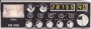
- DX73V

SPECIFICATIONS
RADIO MODIFICATIONS
- DX73V Frequency Conversion
- Channel Chart (After Modification)
- 10 meter FM Mod (28.000 - 29.655MHz)
- Disabling Talkback
- Clarifier Mod
- Roger Beep Tone Mod
ALIGNMENT PROCEDURES
- PLL Alignment
- Transmitter Alignment
- Receiver Alignment
- Alignment Locations
- VCO Frequency Generation Chart Bands: Bands A-D and Bands E-H
SEMICONDUCTOR INFORMATION
- Transistor Voltage Chart
- Integrated Circuits Voltage Chart
- Active Device Function Location Layout (Main Board)
- Semiconductor Datasheets
DIAGRAMS
- DX73V Schematic Diagram (June 23, 2000)
- Frequency Counter PCB Schematic Diagram (EPT210014C)
- Channel Select PCB Schematic Diagram (EPT077V30Z)
- Dimmer PCB Schematic Diagram (EPT55V-51Z)
- SWR PCB Schematic Diagram (EPT360041Z)
- DX73V Inter-connection Diagram
- DX73V Inter-connection Diagram
- Echo / Voice Changer/Robot Schematic ( EPTOSSB50C)
PCB LAYOUT & PARTS
- Main PCB Layout (EPT360014B)
- Mic Jack PCB (EPT360050Z)
- Dimmer PCB (EPT55V-51Z)
- SWR PCB (EPT360041Z)
- Channel Select PCB (EPT077V30Z)
- Display PCB (EPT077V20Z)
- Mode Switch PCB (EPT066V40Z)
- Frequency Counter PCB (EPT210014C)
- Echo/ Robot PCB ( EPTOSSB50C)
CHASSIS, MISCELLANEOUS & MECHANICAL PARTS
- Front View Chassis Parts
- Front View Chassis Parts
- Rear View Chassis Parts
- Rear View Chassis Parts
- Miscellaneous & Mechanical Parts
MIC WIRING
Stock
1- Shield (Ground)
2- Yellow (Audio)
3- Red (Transmit)
4- Black (Talk-Back On / Off)
Astatic (4 wire)
1- Shield
2- White
3- Red
4- Black
Astatic (6 wire)
1- Shield & Blue
2- White
3- Red
4- Black
Yellow NC
Daiwa EM-500
Cobra CA Series
1- Shield & Black
2- Red
3- White
4- Blue
Galaxy DC-521S (4 wire)
1- Shield
2- Yellow
3- Red
4- Black
Galaxy CB-660EI
1- Shield & Black
2- White
3- Red
4- Blue
Sadelta
1- Shield
2- White
3- Brown
4- Green
Turner
1- Shield & Red
2- White
3- Blue
4- Black
Yellow NC