
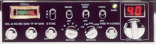
- Galaxy DX Models
- DX77HML
SPECIFICATIONS
RADIO MODIFICATIONS
- DX77HML Frequency Conversion
- Channel Chart (After Modification)
- Extended 10-Meter Frequency Conversion (28.000 - 29.655MHz)
- Clarifier Mod
- Disabling Talkback
- Roger Beep Tone Mod
ALIGNMENT PROCEDURES
- PLL Alignment
- Transmitter Alignment
- Receiver Alignment
- Alignment Locations
- VCO Frequency Generation Chart Bands A-C and Bands D-F
SEMICONDUCTOR INFORMATION
DIAGRAMS
- DX77HML Schematic Diagram (July 11, 2006)
- Active Device Location Diagram (Main Board)
- DX77HML Inter-connection Diagram
- DX77HML Inter-connection Diagram
PCB LAYOUTS & PARTS
- Main PCB (EPT360014B or EPT360014C)
- Mic Jack PCB (EPT360050Z)
- Channel Selector PCB (EPT360022Z)
- Display PCB (EPT360032Z)
- Echo PCB (EPT0SSB50B) (Early Version)
- Echo PCB (EPT0SSB50F) (Used to the end of 2002)
- Echo PCB (EPT0SSB51J) Current Production
CHASSIS, MISCELLANEOUS & MECHANICAL PARTS
- Front View Chassis Parts
- Front View Chassis Parts
- Rear View Chassis Parts
- Rear View Chassis Parts
- Miscellaneous & Mechanical Parts
Mic Wiring
Stock
1- Shield (Ground)
2- Yellow (Audio)
3- Red (Transmit)
4- White (Receive)
Astatic (4 wire)
1- Shield
2- White
3- Red
4- Black
Astatic (6 wire)
1- Shield & Blue
2- White
3- Red
4- Black
Yellow NC
Daiwa EM-500
Cobra CA Series
1- Shield & Black
2- Red
3- White
4- Blue
Galaxy DC-521S (4 wire)
1- Shield
2- Yellow
3- Red
4- Black
Galaxy CB-660EI
1- Shield & Black
2- White
3- Red
4- Blue
Sadelta
1- Shield
2- White
3- Brown
4- Green
Turner
1- Shield & Red
2- White
3- Blue
4- Black
Yellow NC