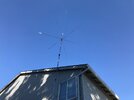
• You can now help support WorldwideDX when you shop on Amazon at no additional cost to you! Simply follow this Shop on Amazon link first and a portion of any purchase is sent to WorldwideDX to help with site costs.
  • A Winner has been selected for the 2025 Radioddity Cyber Monday giveaway! Click Here to see who won!

Weird/different SWR between radios

I definitely need to raise antenna above the roof line.
FYI:
ZEROFIVE-ANTENNAS 10-40 meter MULTIBAND GROUNDPLANE VERTICAL ANTENNA INSTALLATION TIPS MANUAL Unpacking your vertical Your vertical comes shipped in 1 carton with 3 packs inside for model 10-40 . There are 2 radial packs and a vertical element pack. The assembled base section with transformer is the 4th pack. Unwrap the bubble packing from the base section and put it aside. Unpack the vertical section which has 2 tubing piles side by side and slide the tubing into the next smaller size up to the black marks for all the sizes. you will have to alternate between the 2 piles to get the single vertical element. Next slide the whole element into the base section and tighten the clamp. Make sure you do not over tighten the clamps. Unpack one of the radial packs and start with the 3 smaller pieces of tubing and slide them into the next bigger 3 sizes up to the black marks. The next 3 pieces are the inner elements which have a clamp on each end. Slide the sections you just prepared into one end of the inner element up to the black mark. Now you have 3 complete radials. Assemble the next radial pack the same way and you will now have six. MOUNTING Your ground plane will work best mounted in your yard on a pole cemented in the ground. It is best to keep it between 6 to 8 feet off the ground for best performance and to reduce the risk of coming in contact with the ends of the radials. It will also be better for cutting the grass under the vertical. The ground plane accepts up to a 1 5/8 inch outside diameter mast or 1 1/4 water pipe up into the base tube. It is secured by tightening the three 5/16 bolts with a 1/2 inch box wrench. Only tighten the bolts enough to hold the vertical in place. DO NOT OVERTIGHTEN THESE BOLTS.
 
I definitely need to raise antenna above the roof line.
FYI:
UPPORT MAST, GROUND MOUNTING Use a 10 foot length of 1 1/2 to 1 5/8 inch outside diameter strong pipe. This should be cemented 3 feet in the ground and 7 feet sticking out. The hole should be 12 inches diameter and 36 inches deep. Back fill with 2 inches of gravel at the bottom and pack it down. Put your pipe in the center of the hole and plumb it straight. You may want to tie it off so it does not shift while you pour the cement. You can use regular bags of cement to fill the hole up. Once it is dry you are ready to mount your new ground plane vertical. You will mount the base section with the vertical element first. You will need a step ladder to reach the top. Stand the vertical upright and slide it over the top of your mast and tighten the two 5/16 bolts. DO NOT OVERTIGHTEN THESE BOLTS. Next you will be installing the radials. Do one at a time by sliding the big end with the clamp over one of the solid mounting pegs. Tighten the clamp and repeat for the last 5 radials. After the radials are installed, check to see if the feed wire is touching any of the radials. It should be centered between 2 of them. You do not want this wire to touch any metal and arc over to ground. SELECTING YOUR COAX AND GROUNDING Good quality coax is a must for any high power high performance installation. 75 feet is the minimum required length to use for this vertical. Rg-213 coax is best suitable for use with this vertical. It is low in loss and flexible. It is best to use 2 ground rods 8 feet long each, they should driven in 1 foot outside of the edge of the concrete one on each side. Connect them together with #8 wire and run the wire up the mast to the bottom bolt on the base tube. SELECTING A TUNER You will need a wide range tuner for this vertical on all bands. Palstar or LDG has a great line of tuners that will work with this vertical. You can also run a remote tuner at the feed point, but will require a model capable of handling the maximum power you intend to run.
 
What is the input tune, from the Lincoln, SWR meter, amp, amp turned on.
This idea is going to sound nuts , take the top cover off the Lincoln and test again and see if the problem goes away.
The older Uniden 2510/Lincoln chassis had a issue with the radio oscillating at weird random times, removing the cover sometimes made it stop.
Rogerbird has some notes on that I think, a insulator behind the final I believe is the cure.
Do you have a frequency counter?
I don't think you have a antenna problem, I think it is the radio that doesn't like the front end of the amp.


73
Jeff
 
  • Like
Reactions: Woody-202
See the below quote from Rogerbird
"

Cure for High SWR with covers off or on

Usually this problem is caused by the fact that Uniden did not install an insulator between the MRF477 Final and the heatsink.
The mounting tab of the MRF477 (and MRF497) is 'Power' Ground and the heatsink is 'Chassi' Ground.
Meeting through the final can cause a 'RF ground loop effect' which tends to cause the High SWR issue.
The cure is to add an insulator between the Final and heatsink. Be sure to add a thin coat of Thermal Grease to both sides of the insulator.

"
Possibly

73
Jeff
 
This problem also sounds an awful lot like what happens when the amp goes into self-oscillation when keyed up. Could also be generating harmonics which are throwing off the SWR. Could even be a combination of those two things. I missed what kind of amp it is....... there are fixes involving resistors that help stop amp self-oscillation, but as I am by no means an amp expert I will leave that up to those who are.
 
  • Like
Reactions: Cable Guy
What is the input tune, from the Lincoln, SWR meter, amp, amp turned on.
This idea is going to sound nuts , take the top cover off the Lincoln and test again and see if the problem goes away.
The older Uniden 2510/Lincoln chassis had a issue with the radio oscillating at weird random times, removing the cover sometimes made it stop.
Rogerbird has some notes on that I think, a insulator behind the final I believe is the cure.
Do you have a frequency counter?
I don't think you have a antenna problem, I think it is the radio that doesn't like the front end of the amp.


73
Jeff
The antenna system has been installed as per the manufacturers instructions and the SWR on two of the three radios is within the allowable tolerances, what else is left but the radio being the cause of the high SWR?
 
Hi folks! Responses to your recent questions:
  • Antenna base is approx. 30ft. above ground mounted on Rohn HD mast
  • Antenna performs well with tuner.
  • Amp is a new Carl Built 20012C base (2-pill) performs well with other radios inline, no SWR issues
  • I contacted Roger, sending him the Lincoln today
Thank you all for the recommendations & help! Much appreciated!
 

Attachments

  • Zero-Five.jpg
    Zero-Five.jpg
    171.4 KB · Views: 72

dxChat
Help Users
  • No one is chatting at the moment.