Hi I recently acquired a CP 2000 that is in need of repair. The radio has no output power and hardly any recieve at all and was wondering on where I should start on this unit. It looks untouched inside and pretty clean. I hear clear audio on PA but that's about it, last night I heard faint voices on LSB and didn't matter when I changed channels I heard the same faint voices. I can key up a nearby radio and can hardly hear my voice on it same goes when I transmit on the CP2000 the rf meter moves however it's just noise. Any recommendations?

You are using an out of date browser. It may not display this or other websites correctly.
You should upgrade or use an alternative browser.
You should upgrade or use an alternative browser.
-
You can now help support WorldwideDX when you shop on Amazon at no additional cost to you! Simply follow this Shop on Amazon link first and a portion of any purchase is sent to WorldwideDX to help with site costs.
CPI 2000 issues
- Thread starter Danzik
- Start date
sounds like problems in the PLL. not working, not locking up on frequency.
that PLL is big, with discrete components,
that PLL is big, with discrete components,

Like BayouRadioAmplifier said, probably something in the PLL area, because it sounds like it's stuck on a single channel.Hi I recently acquired a CP 2000 that is in need of repair. The radio has no output power and hardly any recieve at all and was wondering on where I should start on this unit. It looks untouched inside and pretty clean. I hear clear audio on PA but that's about it, last night I heard faint voices on LSB and didn't matter when I changed channels I heard the same faint voices. I can key up a nearby radio and can hardly hear my voice on it same goes when I transmit on the CP2000 the rf meter moves however it's just noise. Any recommendations?
One thing to check is the EPROM inputs and outputs. They should change every time you move the channel selector, even if it's only a single bit on each side.
If that's good then your chances of fixing the radio go way up as the rest of the PLL is just standard chips most of which, if not all of, are still available.
Could you possibly go into a little more detail on this as I am new to pll eprom, what type of change am I looking for on the MM 5221 ? Any help would be greatly appreciatedLike BayouRadioAmplifier said, probably something in the PLL area, because it sounds like it's stuck on a single channel.
One thing to check is the EPROM inputs and outputs. They should change every time you move the channel selector, even if it's only a single bit on each side.
If that's good then your chances of fixing the radio go way up as the rest of the PLL is just standard chips most of which, if not all of, are still available.
I am very new to this kind off pll work but if someone can assist on exactly how to checkit I am sure I can get it doneLike BayouRadioAmplifier said, probably something in the PLL area, because it sounds like it's stuck on a single channel.
One thing to check is the EPROM inputs and outputs. They should change every time you move the channel selector, even if it's only a single bit on each side.
If that's good then your chances of fixing the radio go way up as the rest of the PLL is just standard chips most of which, if not all of, are still available.

I do know that there is change on the pins of that chip as I change the channel selector it will go from like - millivolts to positive voltage usually in the +3 to 4vdc rangeLike BayouRadioAmplifier said, probably something in the PLL area, because it sounds like it's stuck on a single channel.
One thing to check is the EPROM inputs and outputs. They should change every time you move the channel selector, even if it's only a single bit on each side.
If that's good then your chances of fixing the radio go way up as the rest of the PLL is just standard chips most of which, if not all of, are still available.
This is all good. Anything in the millivolts should count as a logic 0. Anything above 2.5 to three volts in TTL logic should count as a logic 1. So you're already on the right track.I do know that there is change on the pins of that chip as I change the channel selector it will go from like - millivolts to positive voltage usually in the +3 to 4vdc range
If you look at the schematic Dr_DX posted (thanks Dr!), you'll find that the inputs on the EPROM are pins 21, 1, 2, 3, 19, 18, and 20. I think that's in order from least significant to most significant bit. But I've been wrong before.
The outputs to the programmable divider are pins 11, 10, 9, 8, 7, 6, 5, and 4. Again, going least significant to most significant bit.
Right now you're not concerned with a truth table of what the values for each channel should be, you just want to know if at some point does the value on a given input change and if so, is there a change on the value of any output pins.
You can build a truth table if you want to, BTW. Just record the logic level, 1 or 0, at each input and output pin for each channel. Or the voltage if you're not sure.
Oh, and check that the -8 volts is present on pins 24, 14, and 17. I have a CP400 that was supposed to have a dead EPROM, it was the -8 volts that was missing. Fixed that and it works fine now.
Roger that. The 5221 is a Read-Only-Memory that stores the binary codes that feed into the PLL section. And it's a dead duck without that negative bias voltage. Should survive that side of the power supply shutting down. Just won't work without it.
Oh, and it's not an "E" PROM, just a ROM. No "E", since it can't be erased. No "P" since the programming comes from the optical mask that laid out the circuit patterns on the chip's die. The P would mean programmable.
73
Oh, and it's not an "E" PROM, just a ROM. No "E", since it can't be erased. No "P" since the programming comes from the optical mask that laid out the circuit patterns on the chip's die. The P would mean programmable.
73
Absolutely awesome TM 86 thank you very much for that as now I understand it a little bit more now, I will check for the -8 on those pins at the end of your post ! I did find -8 on one of the test points on one of the boards but it wasn't on this chip. Thanks I will get back with the resultsThis is all good. Anything in the millivolts should count as a logic 0. Anything above 2.5 to three volts in TTL logic should count as a logic 1. So you're already on the right track.
If you look at the schematic Dr_DX posted (thanks Dr!), you'll find that the inputs on the EPROM are pins 21, 1, 2, 3, 19, 18, and 20. I think that's in order from least significant to most significant bit. But I've been wrong before.
The outputs to the programmable divider are pins 11, 10, 9, 8, 7, 6, 5, and 4. Again, going least significant to most significant bit.
Right now you're not concerned with a truth table of what the values for each channel should be, you just want to know if at some point does the value on a given input change and if so, is there a change on the value of any output pins.
You can build a truth table if you want to, BTW. Just record the logic level, 1 or 0, at each input and output pin for each channel. Or the voltage if you're not sure.
Oh, and check that the -8 volts is present on pins 24, 14, and 17. I have a CP400 that was supposed to have a dead EPROM, it was the -8 volts that was missing. Fixed that and it works fine now.
10-4 on that Nomad I did not know that, I do nowRoger that. The 5221 is a Read-Only-Memory that stores the binary codes that feed into the PLL section. And it's a dead duck without that negative bias voltage. Should survive that side of the power supply shutting down. Just won't work without it.
Oh, and it's not an "E" PROM, just a ROM. No "E", since it can't be erased. No "P" since the programming comes from the optical mask that laid out the circuit patterns on the chip's die. The P would mean programmable.
73
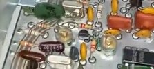
Ok, here are my findings guys. I do have -8 bias on pins 24, 14, and 17. But I did discover this with my magnifier and I looks like it is missing a couple disc capacitors ! One of the photos here with the missing caps is my unit and the other is. Screen shot from another radio. Look where the red pointers are .
Attachments


dxChat
- No one is chatting at the moment.
-
@ Hambones amps:Does anyone know if you can replace the 2290 in a galaxy dx 93t twin turbine with a 2sc2879 red dot? If so, what would have to be tuned?
-
-
@ ShadowDelaware:Hambones the entire amp section would have to be retuned, and the rf transformers re wrapped.