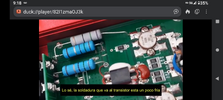
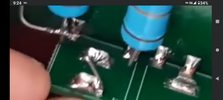
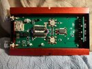
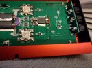
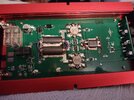
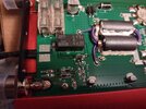
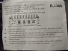
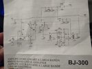
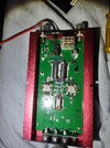
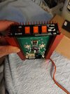
I bought a $100 bj-300 linear(?) amp and attempted 1 time to hook it up and to put it mildly, it did not go well...AT ALL! I've never seen so much screeching feedback , high swr, ant warning lights going off at once! I'm surprised something didn't explode or at least burst into flames! Lol. Anyway, I was a little traumatized by the experience, but enough time has passed that I'm ready to give it another try. I can't help but think that there is a design flaw causing horrible input/output impedence mismatch, or ? Does any one have any experience (i.e. success running one) with these simple surface mount PCB amps, and/or know of any mods to improve them? I'm running a vintage Uniden pc68xl with adj. dead key, a Stryker sra-10 mag mount and digital swr/pwr meter to monitor everything, and the setup performs flawlessly with 1.0 min-1.3 max swr. I'm attaching a few pictures including the amps schematic. Thanks for any help you can give me!
Attachments
-
 IMG_20260116_014531603.jpg1.6 MB · Views: 144
 -
 IMG_20260116_014615911.jpg1.3 MB · Views: 140
 -
 IMG_20260116_014640627.jpg1.2 MB · Views: 132
 -
 IMG_20260116_014610671.jpg1,009.9 KB · Views: 122
 -
 IMG_20260116_013037158.jpg707.3 KB · Views: 126
 -
 IMG_20260116_012848592.jpg911.9 KB · Views: 134
 -
 IMG_20251214_211456580.jpg2.7 MB · Views: 133
 -
 IMG_20260116_015152431.jpg1.8 MB · Views: 142