
You are using an out of date browser. It may not display this or other websites correctly.
You should upgrade or use an alternative browser.
You should upgrade or use an alternative browser.
-
You can now help support WorldwideDX when you shop on Amazon at no additional cost to you! Simply follow this Shop on Amazon link first and a portion of any purchase is sent to WorldwideDX to help with site costs.
Galaxy dx99V2 off 4K on various channels
- Thread starter Chris Lawrence
- Start date
Voltages of both adders and pll will help. There are resistor arrays that can give bad logic on the pins. Maybe even a capacitor array, but idk if your radio has them. I will need to check the schematic when I get home.
Input voltage or voltages of every pin? If all pins, does it matter which channel I’m on?Voltages of both adders and pll will help. There are resistor arrays that can give bad logic on the pins. Maybe even a capacitor array, but idk if your radio has them. I will need to check the schematic when I get home.

MC14008BCP PDF
Part #: MC14008BCP. Description: 4-Bit Full Adder. File Size: 225.3 Kbytes. Manufacturer: ON Semiconductor.
www.alldatasheet.com
Attachments
Yes, voltages of all pins and on a determined channel. Channel 1 if you like.Input voltage or voltages of every pin? If all pins, does it matter which channel I’m on?
MC14008BCP PDF
Part #: MC14008BCP. Description: 4-Bit Full Adder. File Size: 225.3 Kbytes. Manufacturer: ON Semiconductor.www.alldatasheet.com
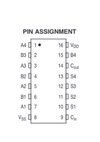
For ch1 band e, the pll program pins should be...
9 high
10 low
11 low
12 low
13 low
14 high
15 high
16 high
17 high
High=>5v, low=<2v
That gives the binary sum of 271..
Edited to correct.
9 high
10 low
11 low
12 low
13 low
14 high
15 high
16 high
17 high
High=>5v, low=<2v
That gives the binary sum of 271..
Edited to correct.
If IC7(IC5) pins match
2 lo
4 hi
6 hi
15 hi
And IC6(IC4) match
2 hi
4 lo
6 lo
15 lo
Then the diode matrix and subsequent band switch is ok. Maybe a bad channel switch.
Sorry if this seems confusing.
2 lo
4 hi
6 hi
15 hi
And IC6(IC4) match
2 hi
4 lo
6 lo
15 lo
Then the diode matrix and subsequent band switch is ok. Maybe a bad channel switch.
Sorry if this seems confusing.
Yes, it is a bit confusing for me. And I didn’t see this until after I got the voltages on channel 20 (which incorrectly reads 27.445). I’m going to post this. I hope the columns match up so it’s legible.If IC7(IC5) pins match
2 lo
4 hi
6 hi
15 hi
And IC6(IC4) match
2 hi
4 lo
6 lo
15 lo
Then the diode matrix and subsequent band switch is ok. Maybe a bad channel switch.
Sorry if this seems confusing.
[edit ic labels—now correct]
IC4————-IC5
1- 0—————-0
2- 7.7—————-0
3- 7.2—————-8.2
4- 0—————-7.7
5- 8.2—————-8.2
6- 0—————-7.7
7- 8.2—————-8.2
8- 0—————-0
9- 0—————-0
10- 8.2—————-0
11- 8.2—————-8.2
12- 0—————-0
13- 8.2—————-0
14- 0—————-8.2
15- 0—————-7.7
16-8.2—————-8.2
Yes pleaseShould I provide other details?
You replaced the adders, and did a very good job soldering them in btw. Need to know what the pll pins read while on channel 1, band E.For ch1 band e, the pll program pins should be...
9 high
10 low
11 low
12 low
13 low
14 high
15 high
16 high
17 high
High=>5v, low=<2v
That gives the binary sum of 271..
Edited to correct.
Last edited:

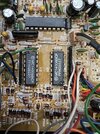
I think your radios has the rci8719 pll, not the mc145106, and circled in green above is a capacitor array. Remove it and see if it goes back on frequency. If so, you can replace it with individual ceramic capacitors. I have seen this once. Circled in blue is resistor arrays I mentioned earlier.
As Brandon pointed out, you have a pin that isn't going high when it should, P2. So, if the capacitor array has a faulty, shorted cap on that pin, when the adder sets that pin high, the CA keeps it low through its short. That array is just a bunch of capacitors sharing a common ground. It should function for awhile without it but it may get erratic, so either replace it with another array after verifying it's faulty, or wire a few ceramics together. I think I have a pic somewhere of what that looks like.

View attachment 75896
I think your radios has the rci8719 pll, not the mc145106.
So, I should switch to Band E channel 1, not 20, and check those voltages and learn them here.As Brandon pointed out, you have a pin that isn't going high when it should, P2. So, if the capacitor array has a faulty, shorted cap on that pin, when the adder sets that pin high, the CA keeps it low through its short. That array is just a bunch of capacitors sharing a common ground. It should function for awhile without it but it may get erratic, so either replace it with another array after verifying it's faulty, or wire a few ceramics together. I think I have a pic somewhere of what that looks like.
Before getting those, I should remove the capacitor array to see if that resolves the issue.
Sound right?
Yes, that's most helpful.So, I should switch to Band E channel 1, not 20, and check those voltages and learn them here.
Yes, remove it first and then check, if the radio is still off frequency, put it back in.Before getting those, I should remove the capacitor array to see if that resolves the issue.
Sound right?
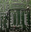
I can see 145106 on that PLL it's not an 8719.View attachment 75896
I think your radios has the rci8719 pll, not the mc145106, and circled in green above is a capacitor array. Remove it and see if it goes back on frequency. If so, you can replace it with individual ceramic capacitors. I have seen this once. Circled in blue is resistor arrays I mentioned earlier.
Ok cool, thanks for identifying it, I couldn't make it out. All I can see on this screen is the ranger name.I can see 145106 on that PLL it's not an 8719.