Just read this thread - very cool discussion. Shockwave's posts about clippers and compression, phase, mic gain, voice peaks, etc. articulate very well a lot of the sentiments that I've had with these types of mods over the years. It's entirely possible to end up with something that's useful, but it requires careful work. As 359 found out, often people that are supposed to know how to do this and make a living as a tech doing these mods even screw it up. That first scope pic that 359 started with was utter crap. It was fun reading how 359 and JD got this thing solved and to see the final results!

You are using an out of date browser. It may not display this or other websites correctly.
You should upgrade or use an alternative browser.
You should upgrade or use an alternative browser.
-
You can now help support WorldwideDX when you shop on Amazon at no additional cost to you! Simply follow this Shop on Amazon link first and a portion of any purchase is sent to WorldwideDX to help with site costs.
-
A Winner has been chosen for the 2026 July 4th Retevis RA89R Giveaway! Click Here to see who won!
2995dx modulation on a scope
- Thread starter GnG8d
- Start date
Just read this thread - very cool discussion. Shockwave's posts about clippers and compression, phase, mic gain, voice peaks, etc. articulate very well a lot of the sentiments that I've had with these types of mods over the years. It's entirely possible to end up with something that's useful, but it requires careful work. As 359 found out, often people that are supposed to know how to do this and make a living as a tech doing these mods even screw it up. That first scope pic that 359 started with was utter crap. It was fun reading how 359 and JD got this thing solved and to see the final results!
This is why I think Worldwide DX is the best forum! You get a lot of good ideas from different people!
I get a lot of crap over this mod because its not what everyone else does! Thanks to you guys for listening to my ideas before shooting them down

You only need one trimmer!
I've been stewing over this while waiting on the new lens and it's almost impossible to find any find of post/socket that will fit on the solder pads ...... anything stocked anyway.
I'm certain that the resistor in parallel does some current sharing, and drops the overall resistance, but is any of that advantages at all? I think I've come to the conclusion that it's not, except maybe some temerature stabilation of the diode. And I don't think that is in issue replacing a resistor that was only rated at .1w. I think I had it in my head that we were dealing with reverse current that could bypass that cap, and needed to see it as proof.
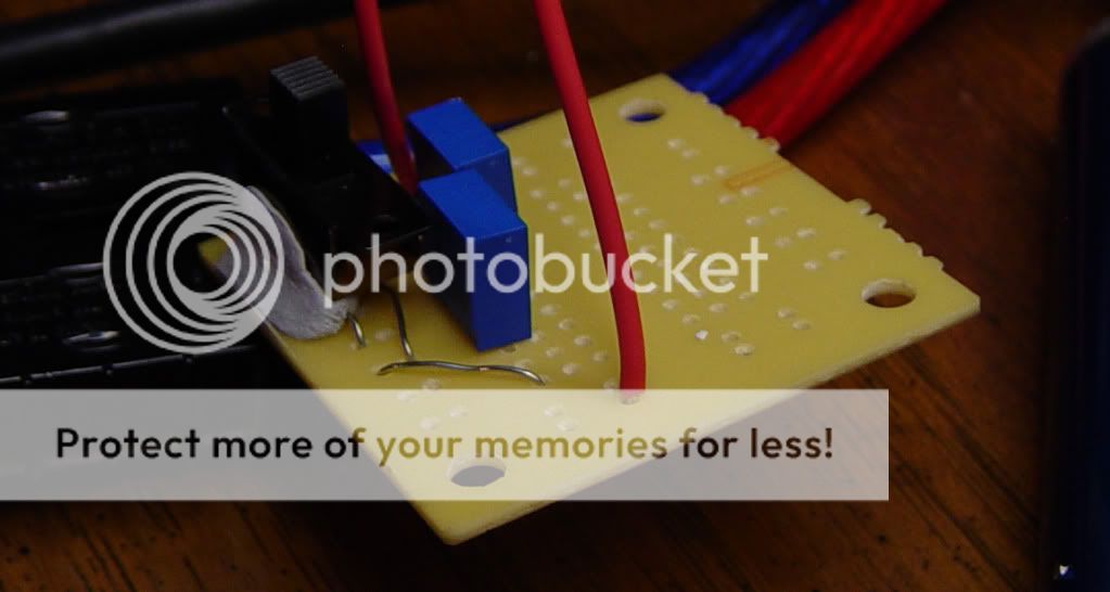
At any rate, I prepped the board a little last night. The solder pad is really the only thing missing, both traces are still there, but man is this shit tiny.
THESE would be nice if they were available anywhere.
Well, I'm about to give up and throw it in the shit can, I've never been able to duplicate the original 160%+/95%- and I should have left it alone instead of removing R292. From the little testing I have been able to do, it still seems that a resistor in parallel with the series resistor/diode is better than just a series resistor/diode across R292. The parallel resistor seems to do more than just drop the forward resistance, and seems to control the flat topping.
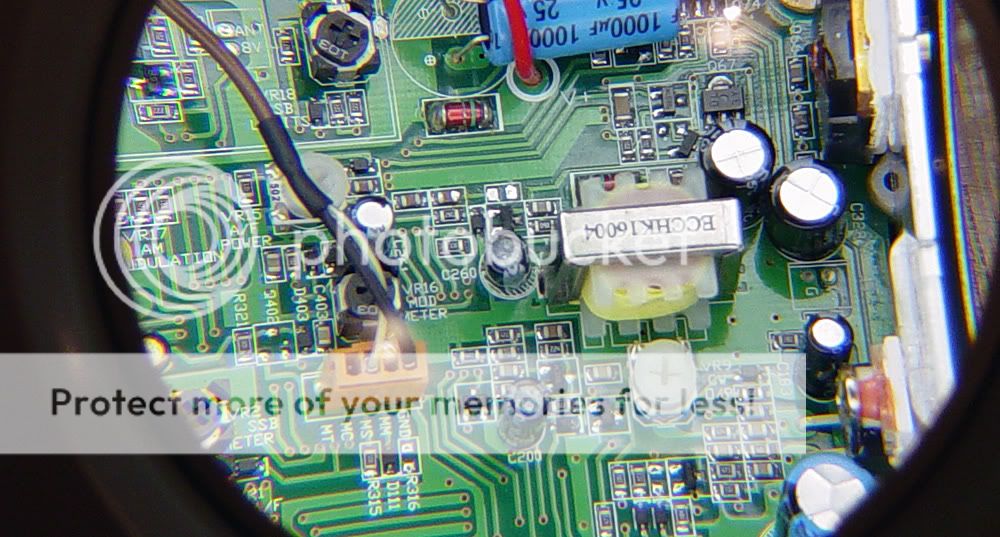
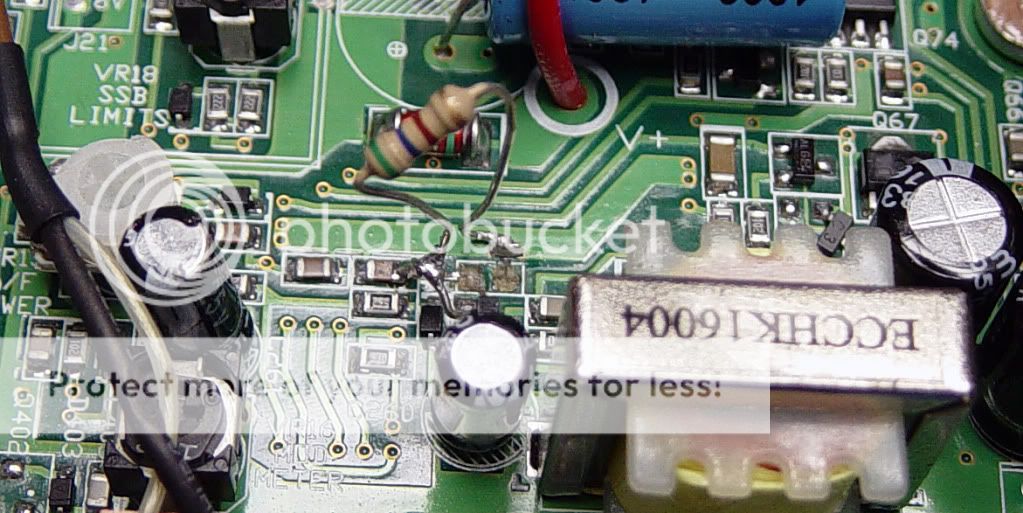
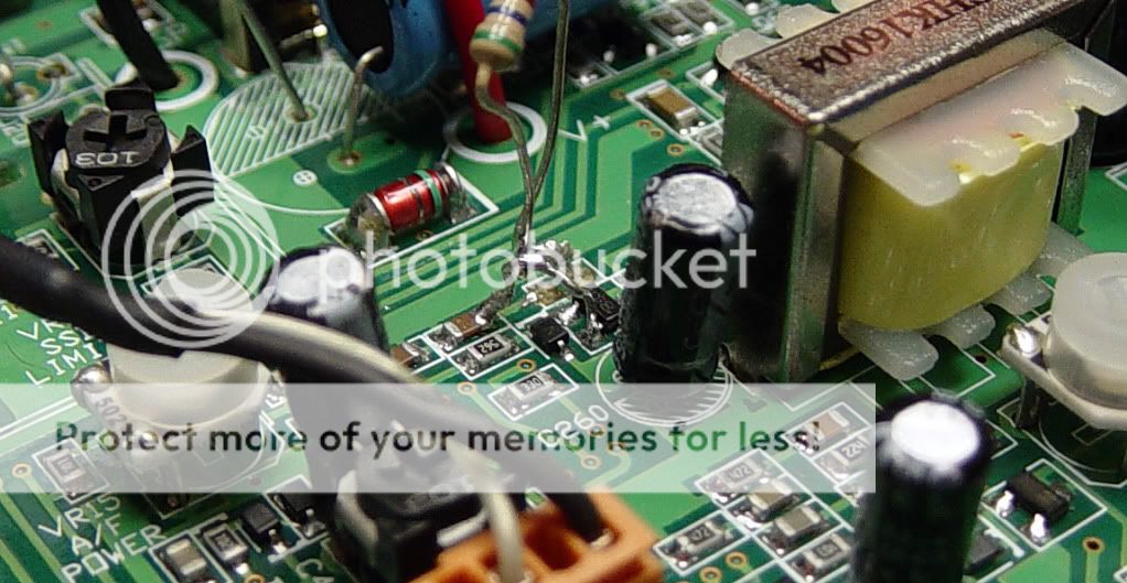
I repaired the pad @R292 with some epoxy and copper foil, but that stuff is just too fine to be doing any testing and I pulled it back off along with the other pad. Hell, the tip of a toothpick dipped in epoxy is bigger than the resistor pad, lmao. The trace from R292 to Q65 is the size of a coarse hair, and goes under Q65. So I used some solid jumper wire to jump from C258 to the emitter of Q65, and scratched a spot open on the busbar or whatever is it. It's much more secure, but now I don't have full power, or any modulation.
I did learn a couple of things though ...... solder braid will lift a solder pad, a shot of whiskey is better than a cup of coffee before working on this miniature stuff and you can only whittle a stick so long before you run out of stick
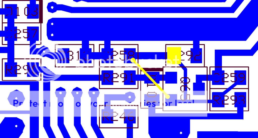
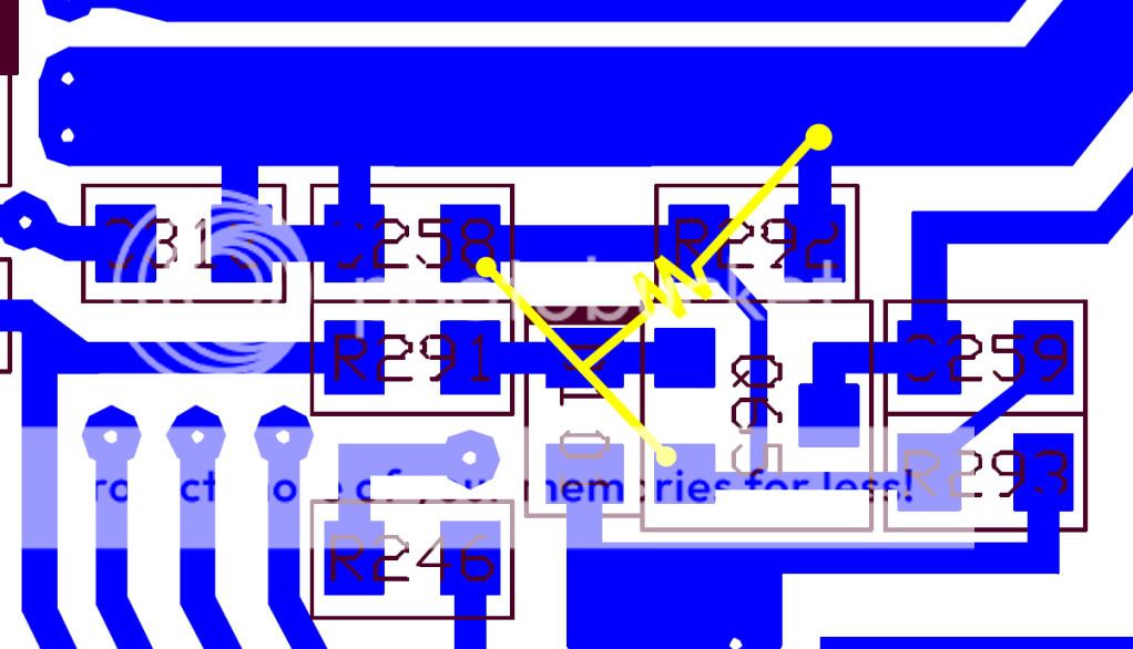
The right side of R292 comes form that thick trace that I scratched open and put a lead on. That lead goes through the diode/resistor on the test board and back to the C258/Q65 jumper. R292 is basically non-existent nowYour jumper from c258 to q65 is wrong, your not completing the circuit with r292! Notice the open pad on the right side of r292.

The right side of R292 comes form that thick trace that I scratched open and put a lead on. That lead goes through the diode/resistor on the test board and back to the C258/Q65 jumper. R292 is basically non-existent now
I know, you need R292 for it to work. Sorry for the quick paint work but im in a rush to get out the door!

Hmmm, I'm not sure I follow. What I've done should be the same, unless I'm missing something? I dug around and found a 560ohm 1/8w resistor, so I took the test board out and threw it in. This *should* mimic the stock circuit, but I get a 50w carrier, no modulation and no control with VR19 or RF power. I must be having a mental block 
Last edited:

Check your connections, you might not be making a good connection or have a broken trace somewhere. Check your work really close for any shorts solder blobs....ect
If you burned up Q65 I dont think you would see a carrier. VR 15 should be your carrier power does that still work?
Does SSB work still?
If you burned up Q65 I dont think you would see a carrier. VR 15 should be your carrier power does that still work?
Does SSB work still?
I've checked and double checked. VR15 takes the carrier from ~60-30w, it should be from ~100-practically 0. Q65 acts normal, I don't think that's it.Check your connections, you might not be making a good connection or have a broken trace somewhere. Check your work really close for any shorts solder blobs....ect
If you burned up Q65 I dont think you would see a carrier. VR 15 should be your carrier power does that still work?
Does SSB work still?
I know it's near impossible to check some components inline, but D98 is acting like it's shorted. It's odd to me that they are using these transistors as diodes in some places.
I've checked and double checked. VR15 takes the carrier from ~60-30w, it should be from ~100-practically 0. Q65 acts normal, I don't think that's it.
I know it's near impossible to check some components inline, but D98 is acting like it's shorted. It's odd to me that they are using these transistors as diodes in some places.
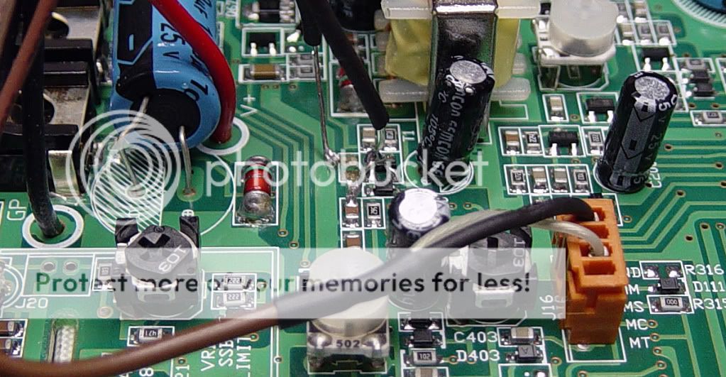
I have a carrier, but VR15 only adjusts it from 20-45w and I have no modulation. VR19 and RF power will not control the carrier either. I've played around with it some, and the RF power will vary the voltage at different points in the radio, but it doesn't change the output.
I've checked some components as best I can, but certainly may have missed something, R289 thru R320, D98 thru D104, C257 thru C264 and I need to do a little more here, but Q65 thru Q71.
Does anyone have a suggestion?
dxChat
- No one is chatting at the moment.