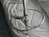
my homebrew 5/8wgp has turned into a .64wgp . heres a few pics ....
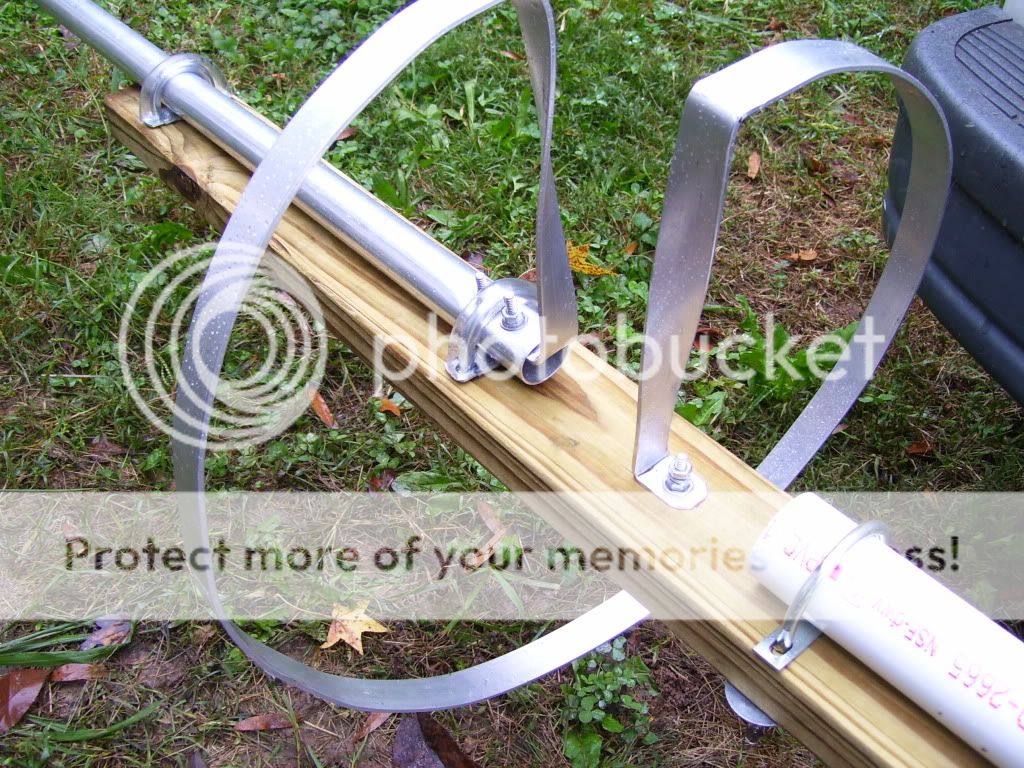
and a closer pic of the tuning ring befor i installed the so-239 .
the dude that helped me had to leave unexpectedly so it doesnt have a coax choke and the feedpoint should have been 1 foot higher so the X hung down to fully straighten the wire ground elements , but its up and its working . their seems to not be enough slack to keep the antenna from preforming well though .
i just have my ears and some trusted locals to go by concerning its performance . the ears are definately better i can hear folks now on their bases that i couldnt hear at all befor and some that were scratchy are cleaner . what the locals are saying is a great example of how inaccurate s-meters on radios are . folks close to me say theres really little to no difference , no suprise due to close proximity . folks farther away say theyre getting up to 4+ additional s-units . i think thats a bit much , LOL . but i am able to talk to a few folks on ground wave barefoot now that i had to use power to be herd by them befor .
so ive got more ears and more signal strength being tx'ed , but certianly not 4 s-units for real . most are saying 1 to 3 more , still a bit generous , but i can tell a difference and so can locals/regulars on the other end .
my vswr has went down since it went up , which seems weird . with the verticle at 22 feet and 22 1/2 feet tall i couldnt get below 1.6 tuning it with the feedpoint 8 feet off the ground . with the verticle at 23 feet i was able to get down to 1.4 across 1-40 and it was 1.4 in the air the day it went up . a few weeks later and its now between 1.2 and 1.2 1/2 across 1-40 . i used noalox on its verticle and tapping point on the ring connections .
i want to make a few changes on it after the holidays . i want to swap the ground wires for horizontal ground elements (more tubing from DXengineering) and change the pressure treated 2x4 to a plastic 2x6 . i also plan to go to 2 inch condiuit for mast and get it a few feed higher . oh , and the coax choke , but i dont seem to have any noise or bleeding problems . my swr doesnt flop around when i mess with the extra coax , but ive read thats not really not a indicator of CMC's .
once again thanks to all who let me pick their brains and helps with their answers and advice .
......................................................... i think some sort of directional loop or H beams will be the project next spring
")
.