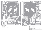
This was from Mike at TS a long time ago.
667v to 500v Conversion
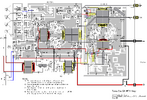
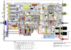
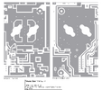
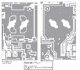
look up and print DX500v and 667V PCB Layouts diagram at CBTricks.com
http://www.cbtricks.com/Amp/txstar/dx400v_dx500v/graphics/dx400v_dx500v_inter_connection_layout.pdf
and DX 667V PCB Layouts
1. remove the driver transistor (2sc2290) and all attached parts
2. remove 100 ohm potentiometer and replace with 250 ohm potentiometer
3. remove resistor R16 (2.7 ohm) from front board and replace with
1.6 or 1.8 ohm.
Note: use same value as is used on rear board for bias circuit
4. rear board at separator toroid - capacitor C20
remove 391 (390pf) and replace with 331 (330 pf)
5. location: under the back right corner of the power switch
cut the pin from the switch to the board
6. location: top of back right corner of the power switch
connect a jumper wire from this pin to green switch, left side,
next-to-last pin
7. remove R2 (10 ohm resistor) from board behind receive switch
8. remove R7 (10 ohm resistor) from delay switch (next-to-last pin
right side)
attach a wire from this pin to left terminal of potentiometer
9. attach a buss wire from second to last pins (R&L) of green
dial-a-watt switch to last pins (R&L) of yellow delay switch
note see diagram on CBTricks.com
10. attach coax wire (6.75") from last pin on top of delay switch (and
ground the coax shield)
attach other end of coax to center of separator toroid (and
ground the coax shield)
11. remove R10 (27 ohm resistor) from potentiometer
12. attach a wire from center terminal of potentiometer to trace on
board behind C43 (22uf capacitor)
(this trace connects to delay switch, right side, third from last pin)
13. remove R5 (5 ohm) and R6 (2.7 ohm) resistors from board next to
delay switch
14. remove right side of R4 (75 ohm resistor) (which is located behind
the green and the yellow switches)
reattach the right side of this resistor to ground pad which is
about 1/2 inch to right of original position.
TEST PROCEDURE
Read bias resistance. Read from base of Toshiba 2879s to ground. Each
board should read 1.3 ohms to ground.
Connect power.
Manually key unit by shorting emitter of key transistor (2907a located
behind relay) to ground.
You must read 0.6 volts dc to ground at each transistor base (both
boards).
With all buttons in, key radio and inject rf power into amp. Glance at
wattmeter for watts and watch combiner toroid for smoke.
If ok, depress yellow and green power buttons to "out" positions.
Apply rf from radio again. 4 watts input should show 200 + watts
output.
Parts List:
1 - 250 ohm potientiometer
1 - dx500v faceplate
1 - 330 pf capacitor
1 - 1.6 or 1.8 ohm resistor
I was cleaning some stuff up and found this, thought I would share.
Jeff
667v to 500v Conversion
look up and print DX500v and 667V PCB Layouts diagram at CBTricks.com
http://www.cbtricks.com/Amp/txstar/dx400v_dx500v/graphics/dx400v_dx500v_inter_connection_layout.pdf
and DX 667V PCB Layouts
1. remove the driver transistor (2sc2290) and all attached parts
2. remove 100 ohm potentiometer and replace with 250 ohm potentiometer
3. remove resistor R16 (2.7 ohm) from front board and replace with
1.6 or 1.8 ohm.
Note: use same value as is used on rear board for bias circuit
4. rear board at separator toroid - capacitor C20
remove 391 (390pf) and replace with 331 (330 pf)
5. location: under the back right corner of the power switch
cut the pin from the switch to the board
6. location: top of back right corner of the power switch
connect a jumper wire from this pin to green switch, left side,
next-to-last pin
7. remove R2 (10 ohm resistor) from board behind receive switch
8. remove R7 (10 ohm resistor) from delay switch (next-to-last pin
right side)
attach a wire from this pin to left terminal of potentiometer
9. attach a buss wire from second to last pins (R&L) of green
dial-a-watt switch to last pins (R&L) of yellow delay switch
note see diagram on CBTricks.com
10. attach coax wire (6.75") from last pin on top of delay switch (and
ground the coax shield)
attach other end of coax to center of separator toroid (and
ground the coax shield)
11. remove R10 (27 ohm resistor) from potentiometer
12. attach a wire from center terminal of potentiometer to trace on
board behind C43 (22uf capacitor)
(this trace connects to delay switch, right side, third from last pin)
13. remove R5 (5 ohm) and R6 (2.7 ohm) resistors from board next to
delay switch
14. remove right side of R4 (75 ohm resistor) (which is located behind
the green and the yellow switches)
reattach the right side of this resistor to ground pad which is
about 1/2 inch to right of original position.
TEST PROCEDURE
Read bias resistance. Read from base of Toshiba 2879s to ground. Each
board should read 1.3 ohms to ground.
Connect power.
Manually key unit by shorting emitter of key transistor (2907a located
behind relay) to ground.
You must read 0.6 volts dc to ground at each transistor base (both
boards).
With all buttons in, key radio and inject rf power into amp. Glance at
wattmeter for watts and watch combiner toroid for smoke.
If ok, depress yellow and green power buttons to "out" positions.
Apply rf from radio again. 4 watts input should show 200 + watts
output.
Parts List:
1 - 250 ohm potientiometer
1 - dx500v faceplate
1 - 330 pf capacitor
1 - 1.6 or 1.8 ohm resistor
I was cleaning some stuff up and found this, thought I would share.
- Hmm seems the Texas Star section of CB tricks is no longer loading......
Jeff

