Low measured resistance from input/output connectors to ground, why?
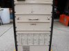
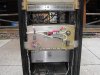
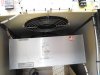
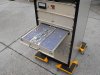
I replaced the input and output connectors on my Larcan (K4DLX kits) and was surprised that I read a short on my ohm meter from the center pin of both connectors to ground. I assumed I had messed up and inadvertently soldered the hot sides to ground. But now my friend tells me he is getting the same readings. It is not shown on the schematic, but there does seem to be a trace that goes from each connector to some kind of feedthrough, not sure what that is, but I assume that somehow accounts for the low resistance.
Could someone enlighten me?
73, Bill NZ5N