• You can now help support WorldwideDX when you shop on Amazon at no additional cost to you! Simply follow this Shop on Amazon link first and a portion of any purchase is sent to WorldwideDX to help with site costs.

Ameritron ALS-1300 HF Solid State Amplifier Review Revisited

Moleculo

Ham Radio Nerd
Apr 14, 2002
9,194
1,674
283
Right at the end of 2010, Ameritron sent me an ALS-1300 solid state, 1200 watt HF amplifier to review. When I received it, I promptly took the AL-800H out of line and put the ALS-1300 in it's place. I've been running it on the Amateur bands and for MARS use since.

First, some pictures.

1568-1295983894-e21e639dfb310d43143faff22b3d846e.jpg


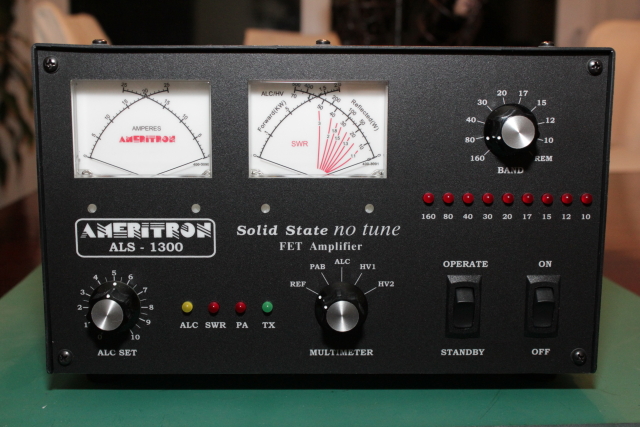
The face of the amplifier is large and the controls are easy to read and use. Once hooked up, the amp is literally a turn-on-and-play deal. One note, you can't just leave the Standby switch in the Operate position and turn it on. You must actively switch the Standby switch to Operate; if it was already in Operate when you turn it on, you must toggle it. This is actually a pretty good minor insurance feature. Then just switch it to the band you want to use and you're ready to go.

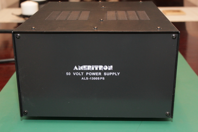
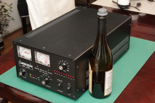
This is the 50 Volt power supply that ships with the amplifier:

1574-1295984003-51612130238161925fbf1494c1cdff16.jpg


The power supply is actually much lighter than I thought it would be and any average sized person can lift it or move it around without struggling. For perspective on the size of the power supply, I stuck a wine bottle next to it:

1571-1295984003-16547a2a3d7cacdcf6c122e950c476a9.jpg


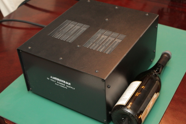
You can also see that the amplifier vents out the top, so you need to keep that area clear.

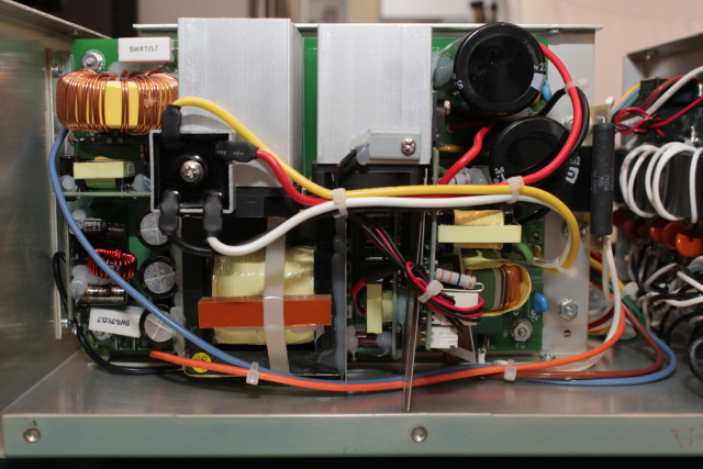
After removing the case, we can get a good look at what's inside the power supply. It is basically two power supplies hooked up in series mounted back to back. Here is one of the supplies:

1572-1295984003-008b3f451ae59e34dae59e9b77a41349.jpg


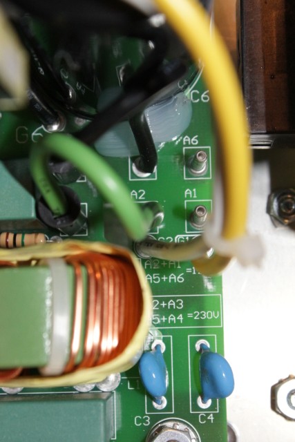
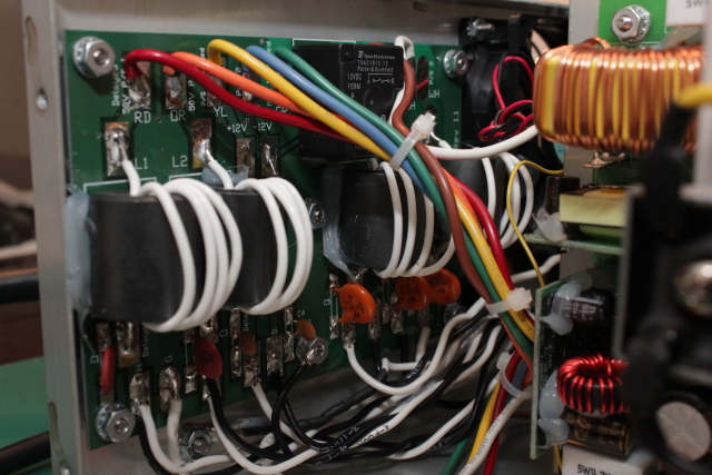
The back of the supply holds the board that interfaces to both the house mains and the amplifier. Also note the large sized torroid RF filters.

1573-1295984003-f7717a969d288584c9e4d10c1e1bbdae.jpg


As a side note, the power supply contains both of the power cords needed to hook up to the supply voltage and the amplifier. The actual amplifier has no power wires.

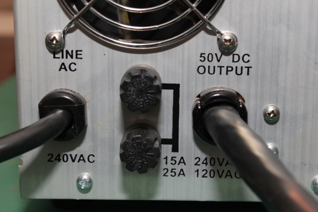
The power supply comes with 15 amp, fast-blow fuses located on the back. You need to supply your own 25 amp fuses if you run it on 120 volts.

1567-1295983839-74ab55e3de98f12b07b60356edabc74a.jpg


Here is the back of the amplifier:
1565-1295983839-80f87fbce00f18f4b731e507954c8196.jpg


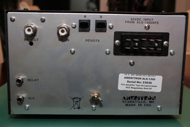
Note the large Cinch Jones connector that interfaces to the power supply harness. Everything else is pretty standard.

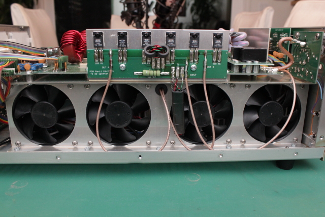
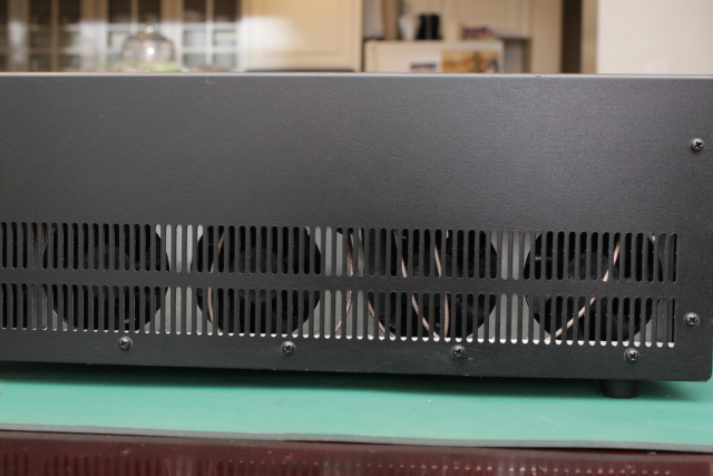
Four large fans blow cool air under the heat sinks and out the other side's exhaust port:
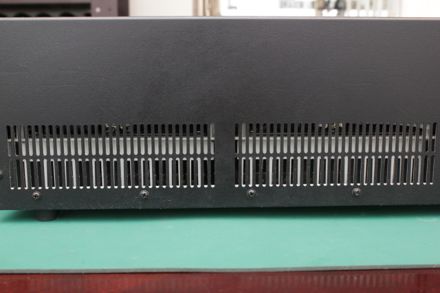
1566-1295983839-1f9861cbdbae8a83782e71e55a2cb203.jpg


Exhaust port:
1558-1295983686-687ebf614b8282009b97b930aea32bef.jpg


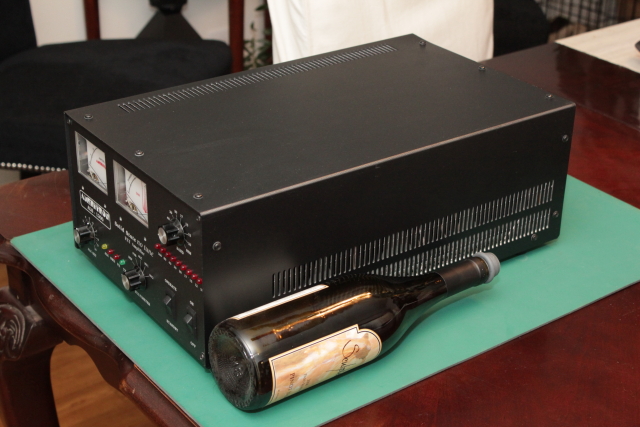
To help gain perspective on the size of the main amplifier, I've again placed the wine bottle next to it:
1563-1295983753-cca4ec072420a95de631328d8a85aa10.jpg


1564-1295983839-002da3269394a7f734a354b481d20912.jpg


The right side meter on the face serves several functions:
1569-1295983894-2a1dc41067797500f0daf507c4a83f6a.jpg


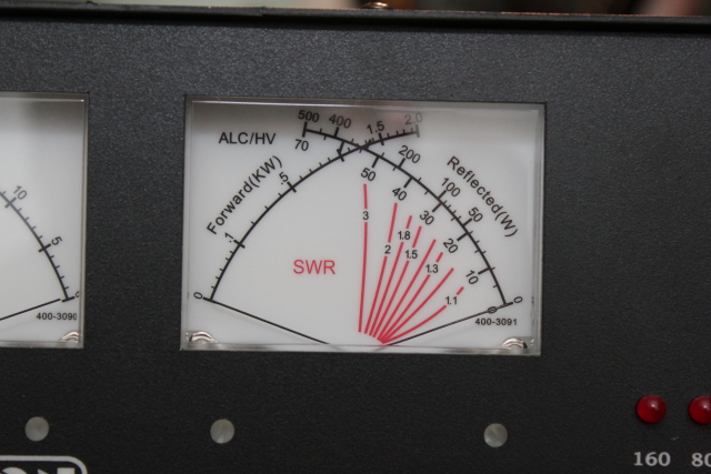
Most obvious is that it acts as a power/swr meter. However, you can turn the knob to the PAB setting and then the right 500 watt scale on the meter shows the difference in power output between PA module A and B (more on the PA modules later). If you switch the meter to ALC mode, you use the 0-70 scale on the right side for ALC voltage, which corresponds to 0-7 volts. If you switch the meter to either of the HV settings, the meter shows the operating voltage of power supply module selected, on a scale of 0-70 volts.

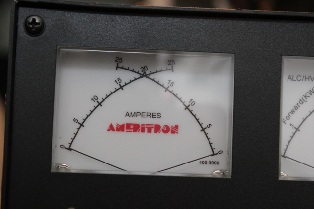
The left side meter shows you the current drawn by each of the power supply modules:

1570-1295983894-cb776886ae0961e9021e66d7ce428053.jpg


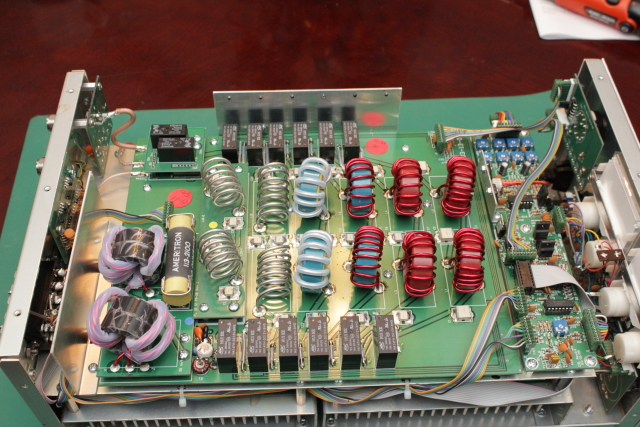
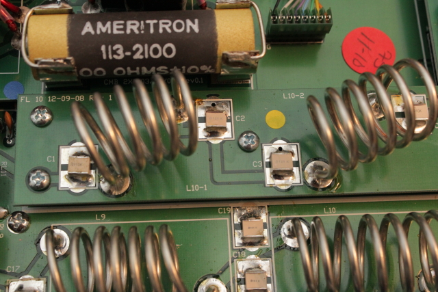
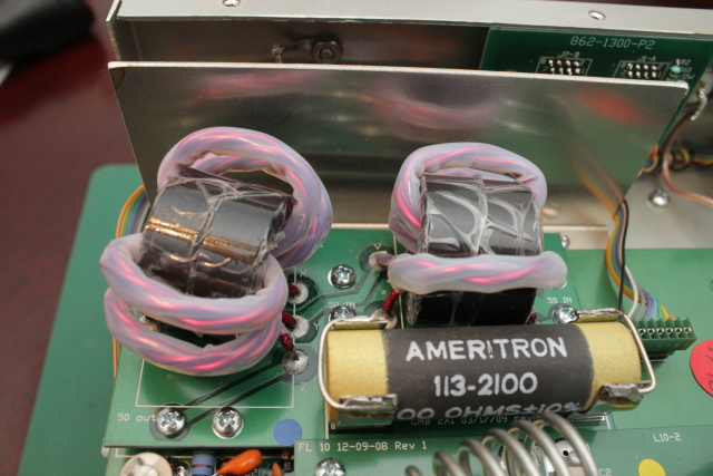
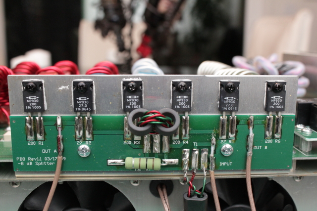
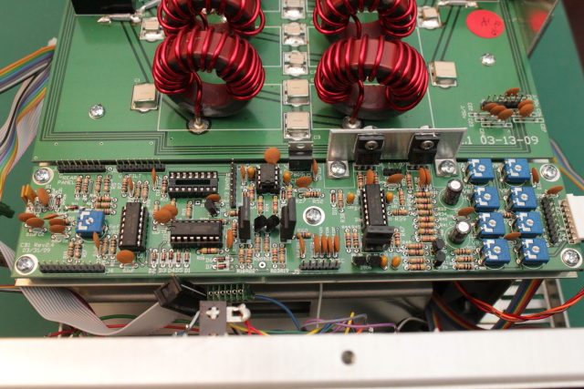
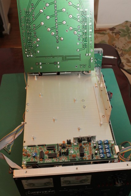
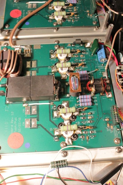
Next, I tear apart the amplifier and show what's inside! :D
 

Inside the Ameritron ALS-1300

Once you've removed about 25 screws on the top cover, the first thing you notice is that the inside of the amplifier is built like a double-decker bus, in two stacked sections. The power amplifier boards are on the bottom and most of the other boards are stacked on top. Here you can see the filter board on top, as well as a few others:

1559-1295983686-4daf109e3f3ee235102eaef6c3c612d6.jpg


Here is the optional 10/12 meter filter that enables the amp to be used on those bands. It's labled FL 10 in the picture and attaches simply with four screws.

1560-1295983753-30513bc8a817bfb160177532f2f2f7f3.jpg


Here is the 2KW combiner board:
1556-1295983530-0c06f6ca4bc585ecc6dad773d665c7a9.jpg


Here is a view of the side where the intake fans are mounted in front of the heat sinks. Notice that the power divider board is mounted vertically right above:

1562-1295983753-bd0a89b0f82c71f861884179c7ad9613.jpg


Here is the close up of the power divider board:
1561-1295983753-1feb3e70ff6801e4bba9fb3935f4307c.jpg


The power divider board essentially splits the input signal evenly between the two PA boards, delivering 10db of isolation between them. This circuit also guarantees 50ohm impedance input to the PA's. The idea is to guarantee that the input is extremely stable.

On the other side of the top deck is the control board. This board has quite a few ribbon connectors (most of them disconnected in this picture) that interface to other parts of the amplifier:

1557-1295983686-237412843c1257927189c37d5fa765c7.jpg


To get at the PA units below, you have to remove all of the boards that I've shown so far. This involves disconnecting all of the interface cables on the control board (remember where they went!), removing the 10m option, the combiner, the power divider, and the filter board. It seemed like about 40 screws! You can then very carefully lift up the filter board to reveal the shield below. If you need to service the PA boards, you will have to de-solder the coax cables fed to this board. For pictures, we can just lift it up and rest it on the case. Here you can see how I did this before the control board was removed:

1554-1295983530-64aa7200e1392c53eeb4cbc43d1a4b7b.jpg


Once you've removed everything in the way, you have a few more screws to remove on the shield/deck to move that out of the way revealing the two 600 watt PA modules below:

1555-1295983530-0528fc33f4d37f5a8be4a15853edd725.jpg


The PA's are run in parallel and each use 4 MRF-150 MOSFETs. I'm no amplifier/circuit design guru, but when I compare schematics it appears to me that the design used is based off of Helge Granberg's Motorola EB104 application which can be found here: High Power Solid State Amplifier.

It was a fun endeavor taking the ALS-1300 half apart, but even the amount of disassembly I did is not for the faint of heart. If you decide to service this amplifier yourself, you really should take a picture of where all of the wire harnesses attach and label the coax cables that will need to be desoldered.

Not shown here are a few miscellaneous boards like the remote interface, meter and relay board.
 
I have seen reviews of these in labs, what I am interested in is the ease of use and of course output power shown on the meter of the average user, you know, mfj watt meters and similar. I mean who really cares what a lab discovers? Get to the meat and potatoes.

If you have a 100 watt radio I am sure it will interest a lot of people.

Just for kicks and giggles, I have an FT-817ND, I sure would like to see what it would do with a low drive.


I'll post a power output table that shows how the amplifier performs at various input levels. As for ease of operation, it couldn't be more simple. Plug it inline, attach a relay cable (and ALC if you need it) to your transceiver, and away you go. Turn it on, flip the band switch to the band you need and TX.
 
Also, How much voltage drop is there at full output? 50v is nominal, What does it dip to?
Also looking at this http://www.datasheetcatalog.org/datasheet/macom/MRF150.pdf There apears to be some play room with 300 watts disipation per device and they seem like they would tolerate a little more voltage. Any chance there is an adjustrment for Power supply voltage? It would be nice to see this amplifier achieve 1500w. I know theres not much diff.....but since you get to play with it!
 
One of my biggest concerns with any amp is the blower noise. How much noise does this amp produce with the multiple fans?


The amplifier is surprisingly quiet, as far as amplifiers go. It is FAR quieter than the blower in my AL-800H. The fan speed in the amplifier is also temperature controlled so that they only turn as fast as needed to keep the amplifier cool. The power supply fan actually makes more noise than the amplifier. The power cable that goes between the power supply and the amp is pretty long; if I had to guess I would say it's about 8 feet long. That means you can separate the supply and get it quite a ways away from your mic position.

Remote Operation
The other option you have is to completely remove the amplifier from your operating position (think garage!) by purchasing one of the optional remote interfaces. You can use the manual ALS-500RC remote switch:

ALS-500RC.jpg


Or you can use the completely automatic ARI-500 remote control:

ARI-500.jpg


Incidentally, these are the same controllers that the ALS-500M uses. If you use either one of these and remove the amplifier from your operating room, your fan noise will be a non-issue.

Actually, I don't find the fan noise to be a problem. Although I usually use a noise gate/downward expander to eliminate background noise, I really don't think it would be something to worry about if you have your mic gain set properly.
 
120 Volt Conversion

The ALS-1300 power supply comes wired for 240 Volt power with a 15 amp plug. The manual indicates that the power supply can run on 120 volt with a slight reduction in CW and RTTY power output. It doesn't really tell you how to do the conversion, although the schematic shows you the labeled jumpers. After a little inspection, I found the jumpers located on each side of the supply:
1553-1295983530-27d3ccee2a3301891d1420f0625c6312.jpg


It's a little difficult to see in the picture (there's a lot of stuff in the way!) but you just jumper A2 & A1 together and A5 & A6 together on each supply and you can run it on 120 volts. It will make sense when you see it in person, although you'll probably need some long needle nosed pliers to reach the jumpers. You will have to replace the power plug yourself, and don't forget to change the fuses on the supply to 25 amp fast-blow fuses.
 
Does the auto tune work quickly ?

Ameritron didn't send the auto switch, so I can't comment other than what is in the manual. I DO have the remote switch head, though because it's the same one used with the ALS-500M. Band switching using the remote head is just as fast as doing it directly on the amplifier, just like you would expect.
 
The power divider board essentially splits the input signal evenly between the two PA boards, delivering 10db of isolation between them. This circuit also guarantees 50ohm impedance input to the PA's. The idea is to guarantee that the input is extremely stable.

Very nice! ;)

73
Jeff
 
I had some time to do a bit of testing tonight and I finished the power output matrix I was working on.

Power was measured on CW using a Bird 43P. I set the input power using either a 50 watt or 100 watt element, checking it on each band, then switching to a 100 watt, 250 watt, 500 watt, 1000 watt, or 2500 watt element as appropriate for the amplifier output.

Here is the power output matrix. Remember, this table is not meant to indicate linearity of the amplifier. Rather, it is published to give everyone an idea on the output to expect at various drive levels.

Band/Drive | 5w | 10w | 25w | 50w | 100w
1.9
|80w|160w|480w|900w|1150w
3.9 |84w|160w|500w|840w|1050w
7.2 |64w|130w|380w|800w|1200w
14.2 |60w|125w|400w|920w|1350w
18.1 |80w|175w|480w|980w|1300w
21.2 |80w|175w|480w|820w|1050w
24.9 |78w|145w|360w|580w|850w
28.5 |70w|150w|380w|720w|1100w

An interesting phenomenon occurred on both amplifiers while testing: The initial power output spikes and then "settles" over about 5-10 seconds. On the high power levels, the difference between key up output power and "settling" power can be as much as several hundred watts. I double checked the output power of the exciter by itself and didn't notice this behavior, so it is definitely something that the amp is producing. While this is not really a problem, it is an interesting observation.

One thing to quote from the manual:

While this amplifier will run more than 1200 watts PEP output, linearity will suffer. Ameritron recommends running no more than 1200 watts peak power for maximum linearity, where this amplifier will have comparable IM performance to the best vacuum tube linear amplifiers.
 
Last edited:
Note:

This review originally began in a different thread here. I uncovered some issues with the amplifier which caused it to fail that took some time for Ameritron to figure out. I've left all of the discussion about the other amplifiers within the other thread and will continue to evaluate the revised ALS-1300 on an on-going basis in this thread.
 
When evaluating products such as linear amplifiers, I know that there is a contingent of people that like to see how what the test reports show. Remember, per FCC rules the spurious transmissions of any amplifier that operates below 30 Mhz must be at least 43 db below the average power of the fundamental emission. Here are the test reports for each of the major bands for the ALS-1300m, with markers shown for both the second and 3rd harmonic.

160 meters, 2nd Harmonic

1778-1315588550-5d224d8fc2be838f536336955e8ba117.jpg


160 meters, 3rd Harmonic


1779-1315588550-20829958a21a1fb127635577cb776319.jpg


80 meters, 2nd Harmonic

1776-1315588523-eb8cfc88f5bde861e158a46a7a997aa3.jpg


80 meters, 3rd Harmonic

1777-1315588550-cfb4617695340b763728b2a9824c675b.jpg


40 meters, 2nd Harmonic

1774-1315588523-7b80dbf2dcadb28945aea37fc0a47f78.jpg


40 meters, 3rd Harmonic

1775-1315588523-9d9e80d0cee75eb5f2de0fb512ab15d5.jpg


20 meters, 2nd Harmonic

1772-1315588497-64403013dac9b9926299141817d0584d.jpg


20 meters, 3rd Harmonic

1773-1315588523-6992399d5c5f1609b6f8c545e41954d4.jpg


17 meters, 3rd Harmonic

1771-1315588497-6ed9af367ff6e4a331346f5e87bdb9b0.jpg


17 meters, 2nd Harmonic

1770-1315588497-48418f42bc998235f6aea6ba27bcfde5.jpg


15 meters, All Harmonics

1769-1315588497-e6676b8f2c79b9c12a23e77743e57808.jpg
 

dxChat
Help Users
  • No one is chatting at the moment.
  • dxBot:
    Tucker442 has left the room.
  • @ BJ radionut:
    LIVE 10:00 AM EST :cool:
  • @ Charles Edwards:
    I'm looking for factory settings 1 through 59 for a AT 5555 n2 or AT500 M2 I only wrote down half the values feel like a idiot I need help will be appreciated