picked up an astatic silver for 10 bucks at an estate sale. doesnt have a cord on it. i have a new cord but want to know if anyone has a wiring diagram or can tell me which wire goes to which pin. also the brown wire is off the circuit board. not sure where to solder it back to on the board. any help?

You are using an out of date browser. It may not display this or other websites correctly.
You should upgrade or use an alternative browser.
You should upgrade or use an alternative browser.
-
You can now help support WorldwideDX when you shop on Amazon at no additional cost to you! Simply follow this Shop on Amazon link first and a portion of any purchase is sent to WorldwideDX to help with site costs.
astatic silver eagle
- Thread starter zebbman
- Start date
- Status
- Not open for further replies.
Should be easy enough to find where the brown wire goes to - it should link to the "-" battery wire on the board.
Trace the wires to their sources.
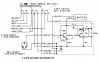
Look at the center/bottom of the schematic - it's right there . . .
Trace the wires to their sources.
Look at the center/bottom of the schematic - it's right there . . .
Find the 9v battery clip. Trace that black battery clip wire back to the board. There should be a trace on the board that leads to one possible solder joint. That is where the brown wire should be soldered to.
As far as putting a new mic cable on it; getting an Astatic replacement cable will help you with the colored wires to the correct reed switch positions.
As far as putting a new mic cable on it; getting an Astatic replacement cable will help you with the colored wires to the correct reed switch positions.
first of all, you need to check the attitude that comes across in your posts.
it makes me not want to help you, but i will anyway.
coming on to a forum asking for help, and then trying to tell everyone how unhelpful their assistance was, is just plain rude.
also that schematic is as easy to read as they get. im not sure how you are able to do the repair but not able to understand the schematic.
to me it seems like you didnt even try.
oh well, here is what you need to know:
from top to bottom, there are nine tabs you need to solder to.
1 will be the top, and 9 will be the bottom.
1. BLACK wire from MIC CORD
2. BLUE wire from MIC CORD
3. RED wire from MIC CORD
4. YELLOW wire from MIC CORD
5. BARE COPPER WIRE from MIC CORD (its the shield, and its wrapped around the white audio wire) and BLACK wire from circuit board. (not the wire coming from the battery, the one coming off of the PC board) both of these wires get soldered to the same tab.
6. BROWN wire from PC BOARD.
7. PURPLE wire from PC BOARD.
8. WHITE wire from MIC CORD.
9. WHITE wire from PC BOARD.
the black wire from the battery connector gets soldered to the PC board right where the BROWN wire connects to it.
the RED wire from the battery connector gets soldered to the tab of the volume pot that connects to a resistor with the colors Brown-Black-Blue on it.
thats about as simple as i can make it, oh, and i got it all from the schematic you said was useless.
good luck,
LC
"is there anyone out there that can tell me what wires go to what post. i dont understand the schematic."
"i have the replacement cord but not being able to read a schematic and not having an existing cord to follow the wiring from all i want to know is which wire goes to which post."
"i have found the schematic a bunch of times but they make no sense to me."
gee, i must not be paying enough attention. how did i miss that it was his eyesight that was the problem?
LC
- Status
- Not open for further replies.
dxChat
- No one is chatting at the moment.