I have a lot of files for MMana.
Various lengths and material.
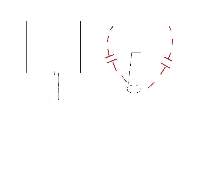
Here an astroplane for 70cm


Astoplane bij PD0G
*
433.0
***Wires***
23
0.0, -0.01, 0.0, 0.0, -0.025, -0.05, 0.0015, -1
0.0, -0.01003, 0.10966, 0.0, 0.0, 0.10966, 0.0015, -1
0.0, 0.0, 0.10966, 0.0, 0.01, 0.10966, 0.0015, -1
0.0, -0.01, 0.11, 0.0, -0.01, 0.0, 0.0015, -1
0.0, 0.02407, -0.05, -0.01, 0.02395, -0.05, 0.0015, -1
0.0, 0.01, 0.10966, 0.0, 0.01, 0.0, 0.0015, -1
0.0, 0.01, 0.0, 0.0, 0.02407, -0.05, 0.0015, -1
0.0, 0.0, -0.3, 0.0, 0.0, 0.10966, 0.0015, -1
0.01, 0.02407, -0.05, -0.01, 0.02395, -0.05, 0.0015, -1
0.01, 0.024, -0.05, 0.024, 0.01, -0.05, 0.0015, -1
0.024, 0.01, -0.05, 0.024, 0.0, -0.05, 0.0015, -1
0.024, -0.01, -0.05, 0.01, -0.025, -0.05, 0.0015, -1
0.01, -0.025, -0.05, 0.0, -0.025, -0.05, 0.0015, -1
0.0, -0.025, -0.05, -0.01, -0.025, -0.05, 0.0015, -1
-0.01, -0.025, -0.05, -0.026, -0.01, -0.05, 0.0015, -1
-0.026, 0.01, -0.05, -0.026, 0.0, -0.05, 0.0015, -1
-0.026, 0.01, -0.05, -0.01, 0.02395, -0.05, 0.0015, -1
0.01, 0.0, 0.27, 0.01, 0.0, 0.0, 0.0015, -1
0.01, 0.0, 0.0, 0.024, 0.0, -0.05, 0.0015, -1
-0.026, 0.0, -0.05, -0.01, 0.0, 0.0, 0.0015, -1
-0.01, 0.0, 0.0, -0.01, 0.0, 0.27, 0.0015, -1
-0.026, 0.0, -0.05, -0.026, -0.01, -0.05, 0.0015, -1
0.024, 0.0, -0.05, 0.024, -0.01, -0.05, 0.0015, -1
***Source***
1, 0
w8e, 0.0, 1.0
***Load***
0, 1
***Segmentation***
400, 40, 2.0, 2
***G/H/M/R/AzEl/X***
2, 3.0, 4, 50.0, 120, 60, 0.0
$$$Taper wire set$$$
1
-0.001, 0, 1.8, 0.015, 1.8, 0.0125, 99999.9, 0.01
Upload a lot of photos.
https://www.qrz.com/db/PD0G
https://pd0g.wordpress.com/
Various lengths and material.
Here an astroplane for 70cm
Astoplane bij PD0G
*
433.0
***Wires***
23
0.0, -0.01, 0.0, 0.0, -0.025, -0.05, 0.0015, -1
0.0, -0.01003, 0.10966, 0.0, 0.0, 0.10966, 0.0015, -1
0.0, 0.0, 0.10966, 0.0, 0.01, 0.10966, 0.0015, -1
0.0, -0.01, 0.11, 0.0, -0.01, 0.0, 0.0015, -1
0.0, 0.02407, -0.05, -0.01, 0.02395, -0.05, 0.0015, -1
0.0, 0.01, 0.10966, 0.0, 0.01, 0.0, 0.0015, -1
0.0, 0.01, 0.0, 0.0, 0.02407, -0.05, 0.0015, -1
0.0, 0.0, -0.3, 0.0, 0.0, 0.10966, 0.0015, -1
0.01, 0.02407, -0.05, -0.01, 0.02395, -0.05, 0.0015, -1
0.01, 0.024, -0.05, 0.024, 0.01, -0.05, 0.0015, -1
0.024, 0.01, -0.05, 0.024, 0.0, -0.05, 0.0015, -1
0.024, -0.01, -0.05, 0.01, -0.025, -0.05, 0.0015, -1
0.01, -0.025, -0.05, 0.0, -0.025, -0.05, 0.0015, -1
0.0, -0.025, -0.05, -0.01, -0.025, -0.05, 0.0015, -1
-0.01, -0.025, -0.05, -0.026, -0.01, -0.05, 0.0015, -1
-0.026, 0.01, -0.05, -0.026, 0.0, -0.05, 0.0015, -1
-0.026, 0.01, -0.05, -0.01, 0.02395, -0.05, 0.0015, -1
0.01, 0.0, 0.27, 0.01, 0.0, 0.0, 0.0015, -1
0.01, 0.0, 0.0, 0.024, 0.0, -0.05, 0.0015, -1
-0.026, 0.0, -0.05, -0.01, 0.0, 0.0, 0.0015, -1
-0.01, 0.0, 0.0, -0.01, 0.0, 0.27, 0.0015, -1
-0.026, 0.0, -0.05, -0.026, -0.01, -0.05, 0.0015, -1
0.024, 0.0, -0.05, 0.024, -0.01, -0.05, 0.0015, -1
***Source***
1, 0
w8e, 0.0, 1.0
***Load***
0, 1
***Segmentation***
400, 40, 2.0, 2
***G/H/M/R/AzEl/X***
2, 3.0, 4, 50.0, 120, 60, 0.0
$$$Taper wire set$$$
1
-0.001, 0, 1.8, 0.015, 1.8, 0.0125, 99999.9, 0.01
Upload a lot of photos.
https://www.qrz.com/db/PD0G
https://pd0g.wordpress.com/
Last edited: