• You can now help support WorldwideDX when you shop on Amazon at no additional cost to you! Simply follow this Shop on Amazon link first and a portion of any purchase is sent to WorldwideDX to help with site costs.

ASTROPLANE best vertical antenna ever?

DB why do you think removing the blue wire causes current distribution to change so much ?

I must have missed your post last night... I'm curious to the specifics of your question, the models I reposted that I think you are referring to don't show a large change in current distribution. The upper vertical with a cap hat and the basket area has pretty much the same distribution as before. The only difference I see with the models I posted is a small change in current flowing on part of the mast.

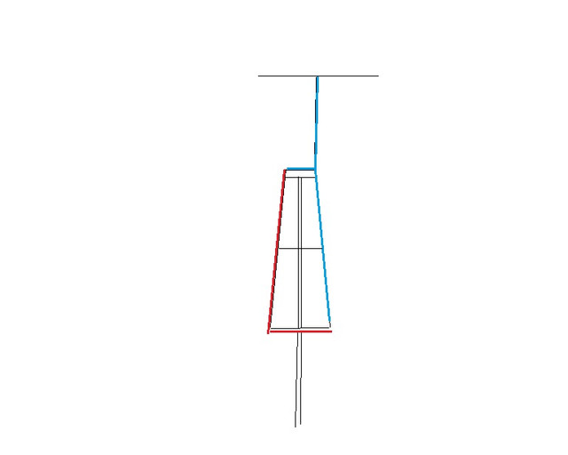
The only thing I can think of that you might be referring to is me talking about mast lengths that aren't optimal, and how the "blue line" has the effect of compensating for this by drawing current from the upper vertical element and cap hat portion of the antenna. Please clarify on what, specifically, you are referring to with this question so I can address it.

I have tuned the mast inside the radials to 187" x 1" showing me the best gain at a low angle. I did the same thing a long time ago when Bob started talking about how this part of the mast system on the A/P effected the tune and performance, but without your tricks...that alone was of little value concerning the match. Without these tricks I see the R value being a bit high even when I could fix the value of X.

will work on this length idea you speak of again using the model you call the Blue Line. That will be another difference no doubt. How sure are you that these tricks in matching are working as intended for these modeling programs?

The best match, be it based on X or SWR, does not imply peak gain. But then I'm sure you know this.

What are you talking about "tricks for matching an antenna"? When it comes to mast length on this antenna design, without the "blue wire" adjusting the mast length makes perfect sense, unless you think that the mast is not an active part of this antenna. With this we are simply adjusting the electrical length of a part of the antenna to match it to the rest of the antenna, which is a sound way matching an antenna, so I don't get this as being a "trick in matching".

I was also curious as to why you used the work "tricks" so what other matching "trick" are you referring to? At first when you mentioned "trick" I thought you meant the ability of 4nec2 to report of the changes in a model over a range of mast lengths, of which I am confident of the results. However, then you mentioned "tricks in matching" and I became confused. I don't recall mentioning any matching tricks when it comes to modeling, especially for this antenna as just putting the wires in to Avanti's specification gives a very good natural match in mu models to begin with.

Does 4Nec2 allow for tapper at wire connections? I use to see Henry using tapper with his Eznec Pro+ models, but of late he has stopped showing as much of his modeling work.

4nec2 has this feature, however I haven't played with it.

I see the sign of a J-Pole in this antenna...except I question how different it would be if the bottom hoop was made into a straight wire...like we see on the J-Pole. I believe that difference needs to be checked out and discussed.

I am out of time at the moment, but please, feel free to share your thoughts, both for and against this idea.


The DB
 
Maybe i missed something DB,
the models show less current in the upper 1/4wave & more on the mast when you remove the blue wire which has very little current flowing on it,

i can't think of a mechanism where removing a conductor that has little current flowing on it would do that unless the mast & parallel conductors are acting like 1/4wave transmission-lines where a short circuit looks like an open circuit and removing it makes it look like a short circuit.

am i missing something in the model?
 
I think the difference in what we are perceiving is based on our points of view more than anything. You seem to be looking at the peak current being different and seeing it as a different current distribution throughout the antenna because of it (correct me if I am wrong here), while I am looking at the distribution of the current in comparison it to the models peak current and seeing that it is close to being the same, or at least very similar throughout most of the antenna.

I don't know that I would necessarily say that either one of said points of view is correct or not, just that they are different.

Now this part is speculation and what said speculation is based on.

A little bit of history with the "blue wire" that may not have made it into the previous discussion and thus may not have been mentioned before. When I use the stock perfect conductors in the model, I am able to get that "blue wire" to have essentially no current, and noticeably less than is shown on said models above, essentially a dark blue wire instead of the lighter blue wire we are seeing above with aluminum elements. When using aluminum elements I cannot get said "blue wire" to report less currents than what it is showing above, which leads me believe that it is the different material that is the cause of this change. In the perfect conductor version of the model, in that case adding and removing said "blue wire" had no effect at all on the antenna (that I remember noticing), assumed the mast was an optimal length.

NOTE: Unfortunately I can't go back and check this as I lost all of my old models due to a series of hardware failures that happened at about the same time, so I have to go on memory here, for now.

So what difference would aluminum make over a theoretical perfect conductor for this antenna? My thoughts lead me to the loss from using aluminum. We have one current node on once side of the "blue wire" and another current node on the other side of the "blue wire". One is right at the feed point, while the other is an electrical 1/2 wavelength from said feed point. Essentially, the other current node has an electrical 1/2 wavelength of travel over aluminum causing some amount of loss between it and the feed point, which causes a difference in magnitudes between said current peaks.

I think that the "blue wire" is drawing off some of the current that would otherwise go to the mast to compensate for this difference. I have already shown the effects of the same thing happening in the other direction to compensate for different non-optimal mast lengths, which in that case has the effect of stabilizing the antenna over a wide range of various mast lengths.

Mind you, at this point this is just speculation, and I am open to thoughts on this.


The DB
 
DB
i am looking at how far down the mast and 1/4wave elements the red colour is on the two models,

I don't know enough about models to speculate about conductor losses,
there are always some losses in conductors so its not a stretch to imagine you could be correct about that been the cause of some current in the blue line.
 
I believe we've been so accustomed to the center feed of coax driving the driven element of a shunt fed antenna that we've forgotten that the braid or outer of the coax will radiate either the top or bottom of a half wave dipole equally well.
There is no doubt what so ever that the AP is a loop antenna fed the exact same way as we feed a loop antenna and it electrically isolates itself into the two halves of a dipole in the same way as a loop does.
The braid is connected electrically to the larger radiator with the top hat via the bracket and the center of the coax is connected electrically to the shorter leg and the basket.
The laws of loop antenna therefore apply, the loop will find it's own inductive and capacitive balance somewhere between the two and a node will appear that is not open circuit but indeed high impedance.
The high impedance node will resist the flow of current but not the flow of voltage and therefore can never be regarded as 'open circuit' nor can it be regarded as 'a dead short for both current and voltage'. It is not a dead short in relation to current but is a dead short in relation to voltage. The blue is the braid radiator and the red is the center feed radiator. Imagine the antenna mounted upside down then you will realise it's nothing more than a straight forward dipole antenna tuned by it's own inductive field which includes the mast.
rad.jpg
[/url][/IMG]
rad.jpg
 
So imagine DB that the feed point of the antenna is highly inductive and where the basket meets the large radiator (red meets blue on my drawing) is high capacitance. The voltage is greatest in the high capacitance node and the current is greatest at the high inductance node (feed).
The reactance of the antenna is as follows: Where red meets blue in the capacitance node, the impedance @resonance is in the mega ohms and the voltage in free space is infinite but in reality not so. At the feed point, the current is maximum where it is the most inductive and this relationship is allowed to continue providing the antenna is resonant at the sine wave it's producing and that sine wave is distributed with equal inductance and capacitance per unit length.
In other words the reactance which creates the nodes can only be so when the antenna is resonant and the electrical length is correct. Play around with it's electrical length or resonance then the reactance will change and the nodes will appear in different places around the antenna and screw up the radiation pattern. That's why if you take away the mast part of the circuit the inductance changes and changes the reactance. It's all about the balance and where you make high impedance appear on this antenna.
 
Last edited:
.....And always remember DB regardless of what you read..the operation of any antenna is dependent on this: The reactance of the tips of both halves of a RF signal towards each other are what actually produce radiation.
It is the high resistance at the tips of the antenna to the flow of current into each other which force the current to swell into an RF pattern. If there is no high impedance there then there is no pattern, capacitance causes high impedance but it can never ever be an open circuit between the tips of an antenna, it can only be resistance or opposition to the tips meeting electrically.
 
Oh wow.

Your understanding of what is happening in an antenna and usage of many of what some would call "big confusing words" is... off... and I'm sorry to say, not just a little bit. If you are talking to someone who isn't that knowledgeable, they may take what you say at face value. However, I'm sorry to say, if you talk like that to someone who has actual knowledge and experience you would only make yourself look bad.

I realize that you are sure of what you think you know, but the way you are using these words, its like you are talking gibberish. I'm not trying to be mean, but with what you have posted, its hard for me to take your "knowledge" seriously. The words and how you used them doesn't conform to any use of the words I have every read or heard. I would ask for sources for what you have stated, but one of the lines you posted makes me doubt I would get anything to back up what you are saying...

You say something is some way regardless of what I read? So your someone who has one of those outlooks... That complicates things in such a way that will only hold you back on your path to understanding antennas. Here are a few questions for you nav2010. Do you really think my knowledge is based solely on what I read? Do you really think I haven't played with many many antennas over the years?

And a big one to ask myself. Should I bother explaining the proper usage of said words and how antennas work and cite sources along the way, or would that be just a waste of my time?


The DB
Rather than bring argument into the discussion DB, explain to the forum how my wording is wrong, explain where i've made critical errors in my assumptions and conclusions. Explain your view and how it differs to mine and others.
 
We'll start with the current maxima on a half wave dipole. Explain to the forum how and why current forms exactly where is does on the antenna, why it never migrates at resonance and what keeps it there when the power from the oscillator increases and decreases?
 
Rather than bring argument into the discussion DB, explain to the forum how my wording is wrong, explain where i've made critical errors in my assumptions and conclusions. Explain your view and how it differs to mine and others.

I wasn't trying to be argumentative, I was genuinely stunned.

If you want, I am happy to explain how your wording is... different... than what everyone else here uses. Being on the same page when it comes to language is required before talking about how antennas work in any way, otherwise we will just talk past each other, so lets just start with words and their use.

So as not to disrupt this thread further I will do this elsewhere, should I create a new thread for this or send a pm, I'll leave that choice to your preference.


The DB
 
Last edited:
I wasn't trying to be argumentative, I was genuinely stunned.

If you want, I am happy to explain how your wording is... different... than what everyone else here uses. Being on the same page when it comes to language is required before talking about how antennas work in any way, otherwise we will just talk past each other, so lets just start with wording an their use.

So as not to disrupt this thread I will do this elsewhere, should I create a new thread for this or send a pm, I'll leave that choice to your preference.


The DB
There is no need to do such a thing. Just explain how in a resonant half wave dipole antenna where the current and voltage are in relation to their respective phase angle's, the relationship of those phase's to the distributed inductance and capacitance, explain where the current maxima is, where current minima is compared to voltage maxima and minima. Just explain why the antenna bottlenecks voltage and current in inductive and capacitive regions of the antenna. The whole thing can be written in less than 100 words.
 
No, i've changed my mind as to the nature of the question, it was too easy. Seeing as the AP is an electrical loop, explain why... when purely resistive circuits have the current and voltage in phase, an RF loop has the voltage and current out of phase, what causes it to be so - involving most of what I asked you above. Phase, current maxima, minima, voltage maxima and minima and distributed inductance/ capacitance (reactance)
 
Nav2010, your image basically looks just like I imagine the A/P working as a CFHW antenna. The red starting at a <>50 ohm point of a 1/4 wave downward projecting element at the mounting bracket, with the voltage end feeding the high voltage point on an orbital hoop that feeds the high voltage point at the bottom portion of the 1/2 wave radiator. This does resemble a loop feeder, but I'm just not sure how the orbital hoop is described in the science.

IMO the orbital hoop would seem to work differently than a simple length of tubing between the two voltage points like we see in an element on a true loop.

On first reading of your posts, so far, I could not see in my minds eye what you were describing in words. I don't think in the terms you used, but that is not your fault. If the picture tells us what your words mean...then we agree this looks to be how the basic A/P works IHMO.

Again, keep us posted on you progress if you are able to test the ideas being discussed here.

I've changed my mind too, but it is not about the same issue. I now don't think it possible to remover the Blue line...at least I have a big question about the model I made trying to see what Eznec predicts.
 
Last edited:
Nav2010, your image basically looks just like I imagine the A/P working as a CFHW antenna. The red starting at a <>50 ohm point of a 1/4 wave downward projecting element at the mounting bracket, with the voltage end feeding the high voltage point on an orbital hoop that feeds the high voltage point at the bottom portion of the 1/2 wave radiator. This does resemble a loop feeder, but I'm just not sure how the orbital hoop is described in the science.

IMO the orbital hoop would seem to work differently than a simple length of tubing between the two voltage points like we see in an element on a true loop.

On first reading of your posts, so far, I could not see in my minds eye what you were describing in words. I don't think in the terms you used, but that is not your fault. If the picture tells us what your words mean...then we agree this looks to be how the basic A/P works IHMO.

Again, keep us posted on you progress if you are able to test the ideas being discussed here.

I've changed my mind too, but it is not about the same issue. I now don't think it possible to remover the Blue line...at least I have a big question about the model I made trying to see what Eznec predicts.
Eddie, my wording is where people disagree. The question is - what does the oscillator see during TX?
Now, on a half wave dipole we have a low impedance, high current, inductive part of the antenna at the feedpoint while at the tips we have low current, high voltage, capacitive and high impedance. The reactances cancel each other out and the oscillator see's a resistive load because of the cancellation...but and this is a big but.....what is the relationship of the tips of such an antenna to each other. Now most believe it is open circuit but I don't, I believe it is at high impedance for nearly all of the phases and I believe so because of the phase shift between voltage and current.
 
Last edited:

dxChat
Help Users
  • No one is chatting at the moment.
  • dxBot:
    Tucker442 has left the room.
  • @ BJ radionut:
    LIVE 10:00 AM EST :cool:
  • @ Charles Edwards:
    I'm looking for factory settings 1 through 59 for a AT 5555 n2 or AT500 M2 I only wrote down half the values feel like a idiot I need help will be appreciated